
Select from the process outward
Industrial furnace selection begins with what must happen to the material, not with an enclosure photograph or maximum-temperature label. A useful specification connects the material and load to a complete thermal cycle, process environment, usable space, handling method, controls, utilities and evidence of acceptance. The closest furnace family can then be identified without forcing the application into an unsuitable model.
1. Define the material and intended change
Identify every material exposed to the cycle, including workpiece, powder, compact, coating, fixture, boat, tray, crucible and temporary process material. State the intended change in process terms. Include available safety information and known sensitivity to oxidation, contamination, volatilization, thermal shock, dust, reactive gas or by-products.
2. Write the complete thermal cycle
Provide the starting condition, required working temperature, ramp stages, intermediate and main holds, controlled cooling, safe unload condition and expected operating frequency. Distinguish the required working condition from any equipment maximum. If different process stages need separate temperatures or axial positions, show them on a simple cycle or zone drawing.
3. Define the atmosphere through heating and cooling
State whether the load can be processed in air or requires inert gas, reactive gas, purge, controlled flow or reduced pressure. List gases, purity objective, flow direction, pressure objective, evacuation and backfill sequence, exhaust destination and known by-products. The atmosphere boundary includes the chamber or process tube, seals, valves, pumps, gas train, instruments and permitted opening sequence.
4. Dimension the real usable load space
Send the maximum workpiece or batch dimensions and mass together with fixtures, supports, trays, boats, crucibles, setters, thermocouples and handling clearances. Internal volume alone is not usable capacity. Allow clearance from doors, walls, elements, radiation shields, sensors, tube ends and moving mechanisms.
5. Choose the material-handling route
Describe whether the load is front-loaded, top-loaded, raised into the chamber, moved on a trolley, placed inside a process tube, suspended vertically, rotated, fed continuously or pressed during heating. Include loading tools, lifting equipment, travel, feed, discharge, collection and operator-access requirements.
6. Compare furnace families by the governing requirement
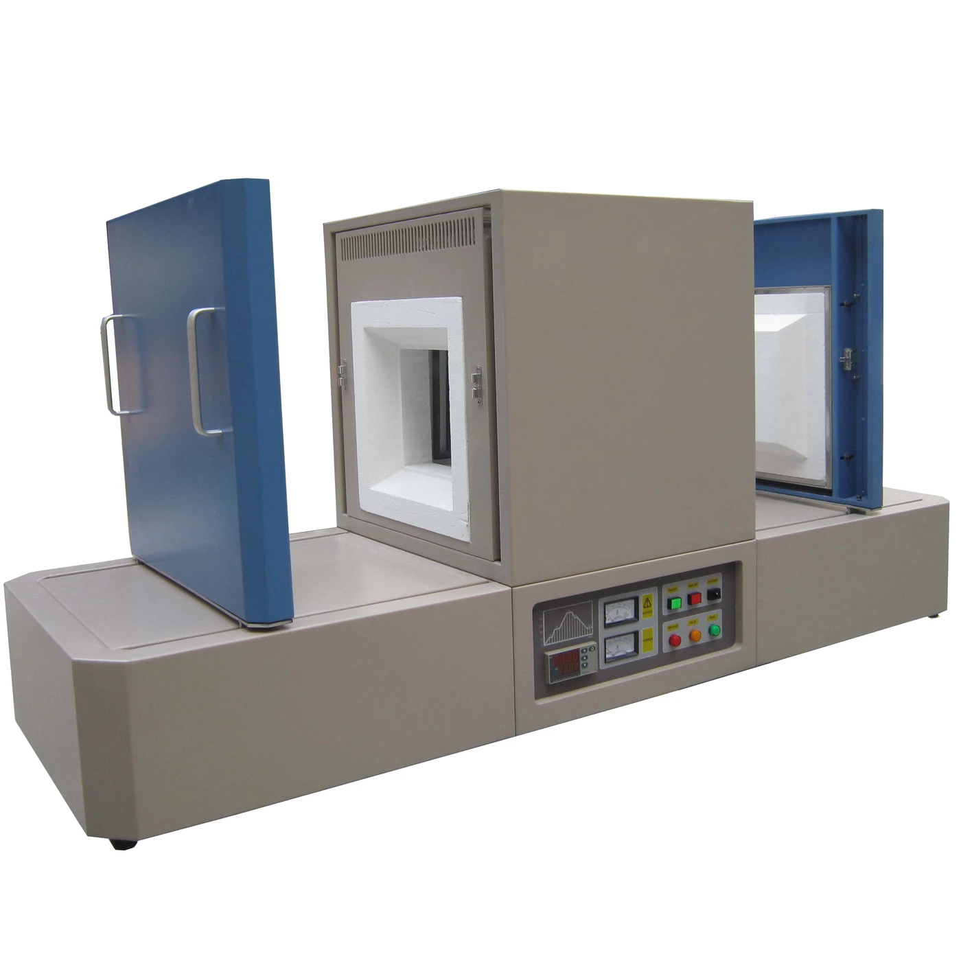
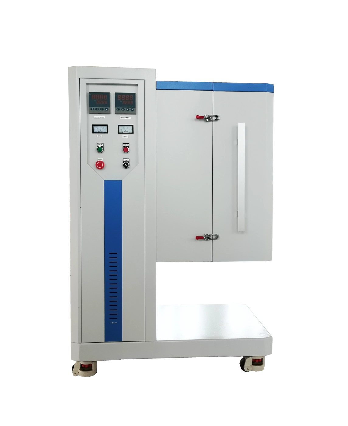
- Muffle & Box Furnaces for compatible enclosed batch loads and general chamber processing.
- Tube Furnaces when a process tube, defined axial position, gas path or tube-based sample handling governs the design.
- Rotary Tube Furnaces when powered tube rotation and controlled powder or granular movement are process functions.
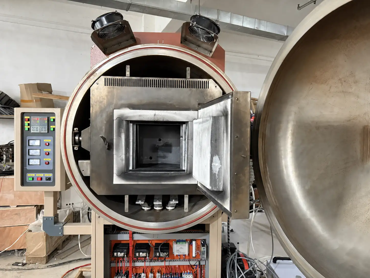
- Vacuum & Atmosphere Box Furnaces for sealed batch loads requiring coordinated chamber, vessel, pumping or gas equipment.
- Trolley Hearth Furnaces for large, heavy or awkward batches prepared on a rail-guided movable hearth.
- Vacuum Hot Press Furnaces only when a defined tooling stack and compressive load are required during heating.
Specialized dental, CVD, PECVD, rapid thermal, brazing, crucible and alternative loading routes should be selected from their distinct process requirements rather than grouped under a generic high-temperature category.
7. Define temperature evidence and control
State whether furnace-controller regulation is sufficient or whether the project needs load thermocouples, a temperature profile, additional zones, pressure or flow records, recipe control, alarms, communication or exported data. The controller sensor does not automatically establish the temperature reached by every workpiece.
8. Confirm utilities and installation conditions
Provide voltage, phase and frequency together with available gases, cooling water, compressed air, exhaust, ventilation and network or data interfaces. Include doorway and aisle dimensions, floor and foundation limits, ceiling height, room temperature, service clearances and the route used to move the equipment into position.
9. Separate equipment scope from facility scope
List which pumps, gas controls, flanges, valves, exhaust components, cooling equipment, loading tools, fixtures, data systems, installation work and commissioning support are expected within the supply boundary. Define facility responsibilities and any applicable site requirements before the proposal is finalized.
10. Establish acceptance before ordering
State which drawings, inspections, functional tests, temperature evidence, pressure or leak checks, control demonstrations, documentation and packing checks are required. Acceptance criteria should match the configured equipment and agreed test conditions; they cannot be inferred from a different furnace or unloaded demonstration.
Industrial furnace selection checklist
- Material, starting form, process objective and safety information
- Working temperature and complete ramp, hold and cooling cycle
- Air, gas, flow, pressure, pumping, purge and exhaust requirements
- Workpiece, fixture, batch dimensions, mass and throughput
- Loading, movement, feed, discharge and collection method
- Temperature, pressure, flow, control, data and acceptance evidence
- Power, utilities, room, access and service clearances
- Equipment, facility, installation and commissioning supply boundaries
- Destination, documentation language and applicable site requirements
After choosing the closest route, use the Furnace RFQ Checklist to prepare the information for technical review.