
Coordinate heat, force and process environment in one system
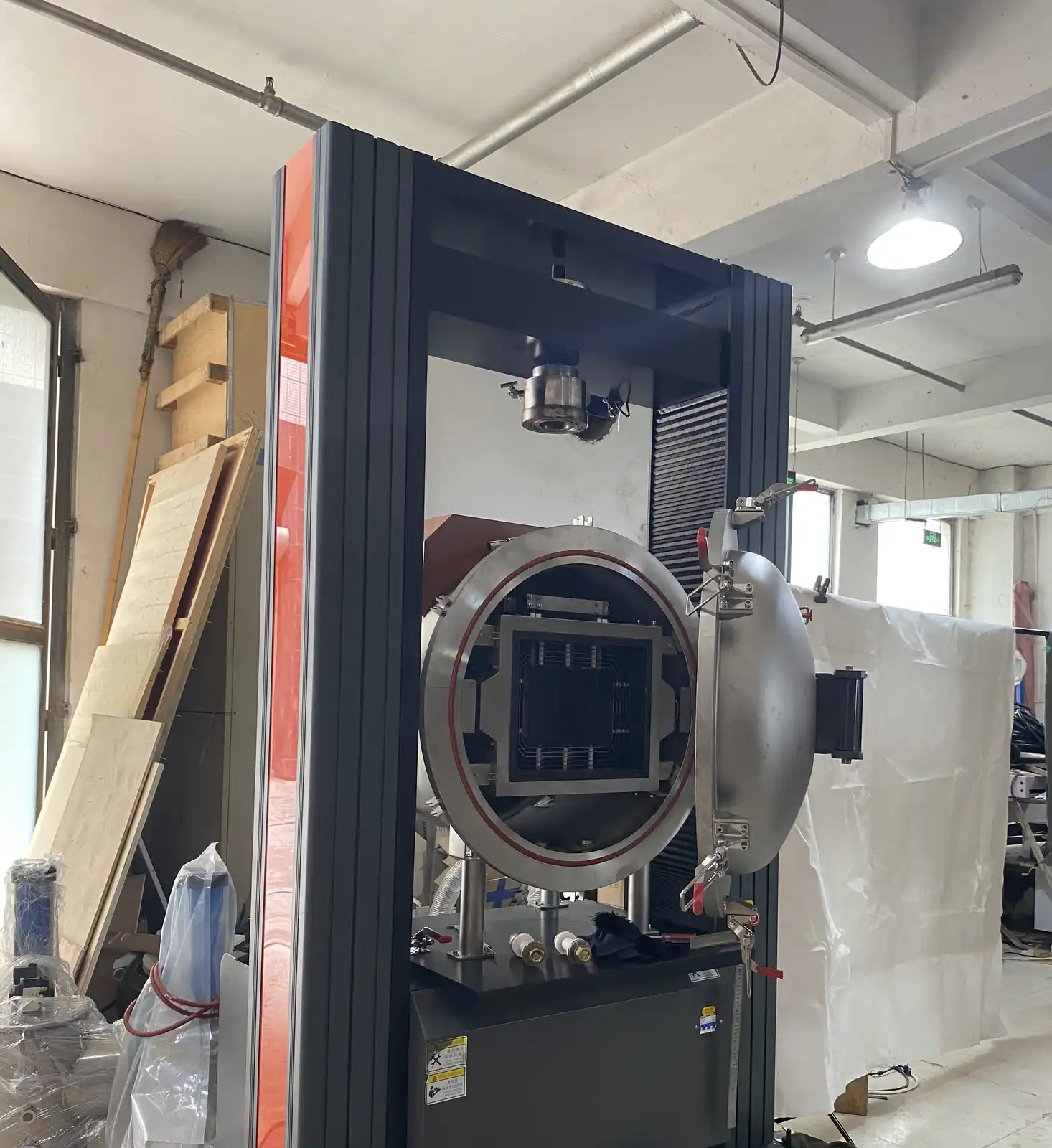
A vacuum hot press furnace combines a heated chamber with a mechanical load path inside a sealed process vessel. The material, tooling, ram or platen interfaces, heating arrangement, vacuum or gas system, cooling and controls influence one another. Selection therefore begins with the complete process schedule rather than an isolated temperature, force or vacuum value.
Describe the material stack and tooling assembly
Provide the material form, starting dimensions and the complete stack from upper load interface to lower support. Identify die, punch, spacer, release layer, tray and insulation materials together with their dimensions and expected temperature exposure. State contamination restrictions, outgassing concerns and any available process-safety information. Pyrocore does not infer a material result from equipment photographs alone.
Distinguish applied force from pressure on the sample
Required machine force and pressure at the workpiece are related through the real loaded area and tooling arrangement; they are not interchangeable labels. Send the contact area, pressing direction, requested force or sample pressure, and how that value changes during heating, holding and cooling. Include preload, maximum travel, expected displacement and any requirement to record force or position.
Dimension the load path through the sealed vessel
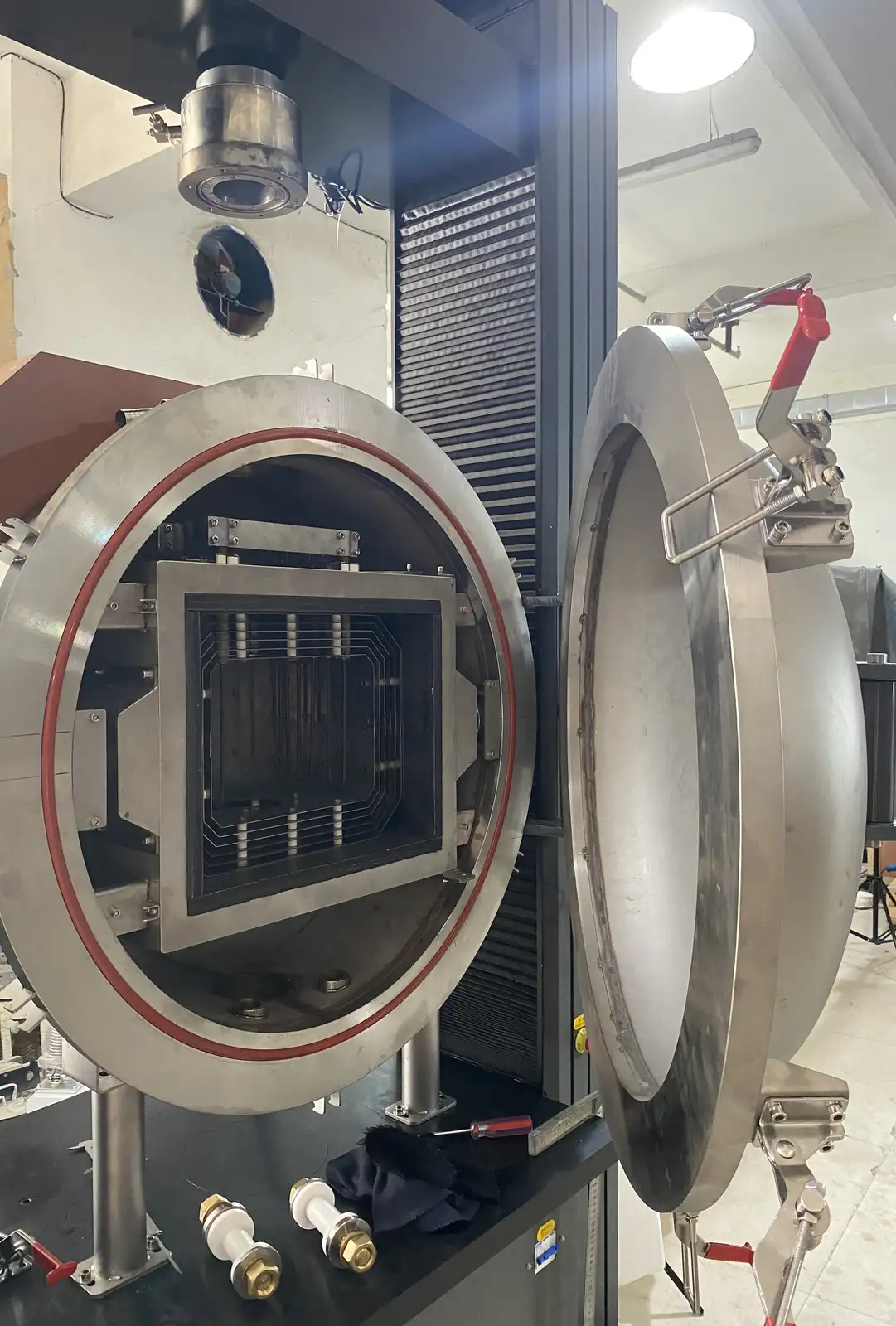
The frame, actuator, ram, feedthrough, platens, tooling and lower support form one mechanical load path. Provide the maximum tooling envelope, pressing axis, available clearance, stroke and loading sequence. The vessel door, hot zone and ram feedthrough must allow assembly and removal without transferring unintended load to heating elements, insulation or sealing surfaces.
Build the hot zone around tooling and measurement access
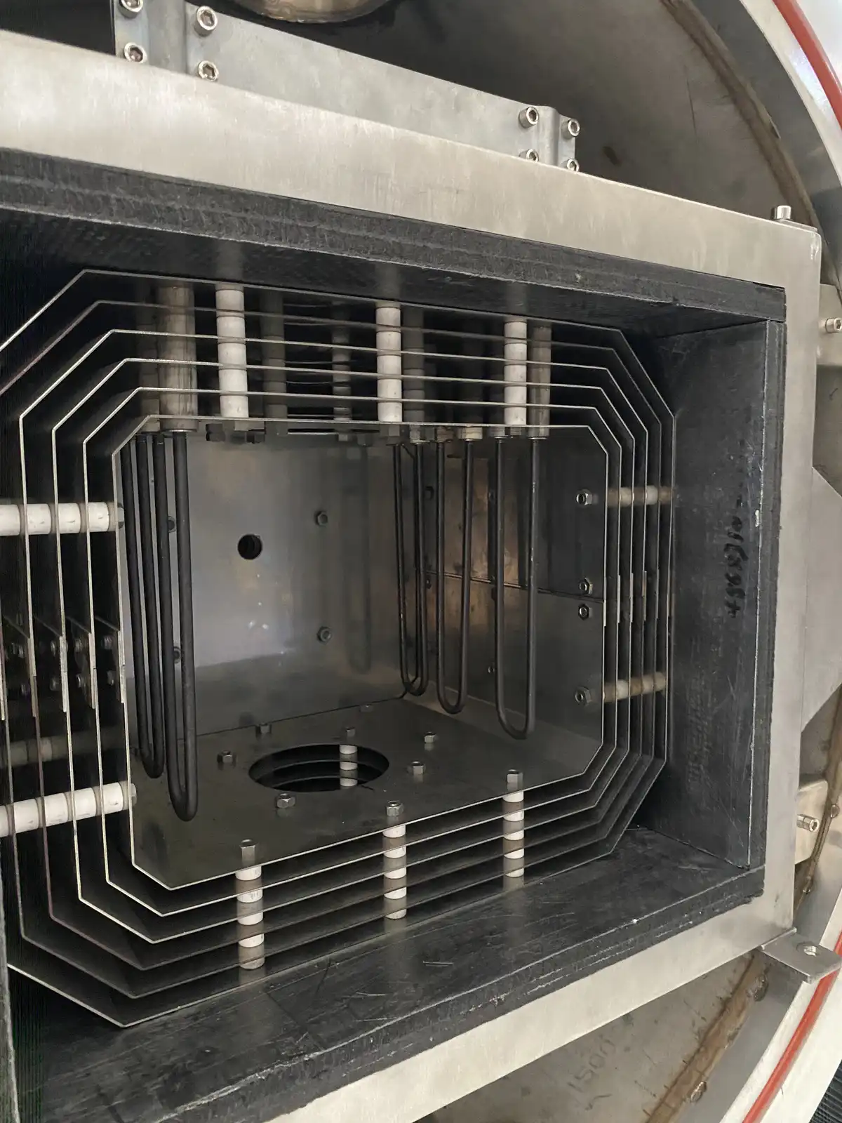
Heating elements, radiation shields or insulation, support structure and sensor positions are selected around the tooling envelope and process schedule. State the required working temperature and where temperature evidence is needed: furnace zone, tooling, sample vicinity or another defined point. Controller regulation does not by itself prove the temperature distribution within the tooling stack.
Define the vacuum or controlled-gas sequence
Describe the initial condition, evacuation, purge, backfill, process gas, pressure changes, cooling environment and final venting sequence. Include gas purity or contamination limits where relevant, permitted exhaust route and any process by-products. Achievable pressure is a property of the complete configured vessel, seals, feedthroughs, pumping system, gas load and operating state, not a transferable claim from another machine.
Coordinate ram feedthrough, seals and cooling
A moving load path through a sealed process boundary requires the feedthrough, seal, alignment and cooling arrangement to be reviewed together. State expected stroke, movement frequency, process temperature, environment and acceptable maintenance access. Identify available cooling water and site limits, and describe how the tooling and vessel may be cooled before unloading.
Specify force, displacement and temperature evidence
Define which variables must be displayed, controlled, recorded or exported. Possible project signals include furnace temperature, additional thermocouples, applied force, ram position or displacement, vessel pressure, gas flow and cooling status. Required accuracy, sampling interval, recipe steps, alarms and data-retention expectations should be submitted for review instead of assumed from the control interface.
Establish safe process states and interlocks
The permitted relationship between vessel closure, pressure condition, heating, force application, actuator movement, cooling and venting must be defined. Door or lid status, pressure measurement, temperature limits, cooling flow, actuator travel and emergency response may form part of the interlock strategy. Site-specific risk assessment and applicable equipment requirements remain part of the final engineering review.
Plan loading, cleaning and service access
Explain how the tooling stack is assembled, supported, transferred into the vessel and removed after processing. Include lifting points, maximum component mass, glove or cleanliness needs, sealing-surface protection and the preferred cleaning method. The installation envelope must allow access to the vessel door, ram or actuator, feedthrough, pumps, valves, sensors, heating terminals and cooling connections.
Information required for a vacuum hot press furnace RFQ
- Material name, starting form, dimensions and available safety information
- Complete tooling-stack drawing with materials and contact areas
- Working temperature and full heating, holding and cooling schedule
- Required force or sample pressure, pressing direction and time profile
- Stroke, displacement or densification-measurement requirement
- Vacuum, purge, process-gas, backfill and venting sequence
- Temperature, force, position, pressure and gas data requirements
- Contamination, outgassing, cleaning and exhaust constraints
- Power, cooling water, compressed gas and other site utilities
- Loading equipment, room access, footprint and service clearance
- Destination, installation scope and applicable site-safety requirements
For a sealed batch process without applied compression, compare Vacuum & Atmosphere Box Furnaces. Joint-heating projects can review Vacuum Brazing Furnaces. Related connection hardware is available through Vacuum Flanges & Fittings, while process-specific temperature sensing begins with Industrial Furnace Thermocouples.