
Move the load platform instead of forcing the load through the doorway
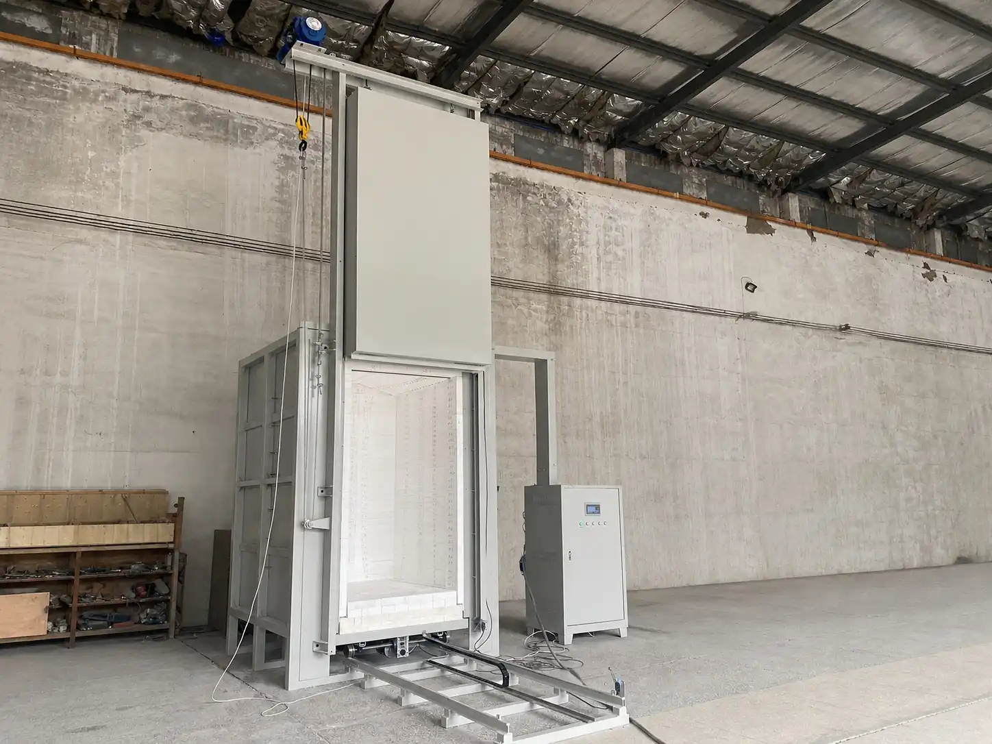
A trolley hearth furnace uses a movable refractory-lined platform as the furnace floor and load carrier. It is a practical route when a batch is too heavy, tall, wide or awkward to place safely inside a conventional front-opening furnace. The trolley, rails, lifting door, chamber and control sequence are therefore specified as one material-handling and thermal system.
Define the load and fixture before sizing the chamber
Provide the maximum part or batch envelope together with its mass, centre of gravity and support arrangement. Include trays, setters, racks, fixtures and lifting points because they occupy usable space and add thermal mass. The real usable chamber is established after clearances from the door opening, chamber walls, heating elements, thermocouples and trolley insulation are allowed.
Treat the trolley as part of the heated system
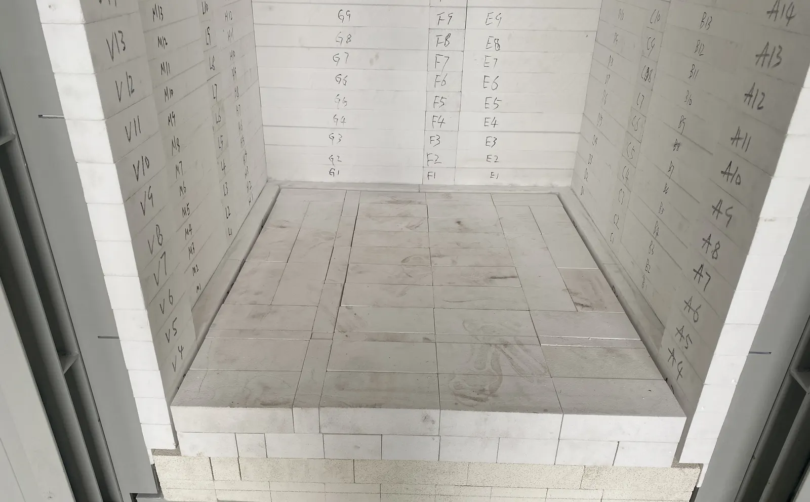
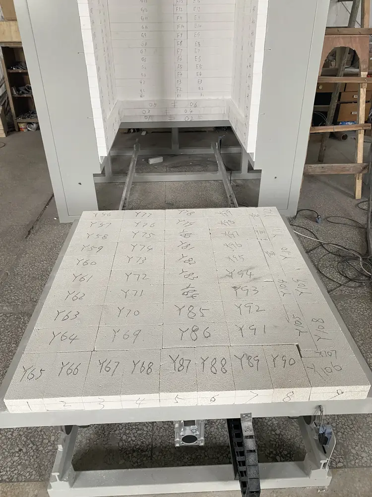
The trolley is not only a transport cart. Its refractory deck closes the lower chamber boundary and supports the load during the full thermal cycle. Hearth construction, wheel position, frame stiffness, insulation depth and the interface with the furnace body must be reviewed against load distribution, temperature exposure, thermal expansion and repeated movement. Point loads and off-centre loads should be identified in the inquiry.
Coordinate rails, drive and floor conditions
State whether the trolley will be pushed, pulled or driven, and describe the available loading equipment. Rail length, gauge, alignment, stops and approach area must fit the installation floor. The proposal also needs the floor level, foundation limits, doorway and aisle dimensions, overhead restrictions and the route used to bring the assembled equipment into position.
Qualify the vertical lifting door and opening sequence
A vertically moving insulated door clears the front loading path, but it adds an overhead movement and support envelope. Confirm the clear opening, required lift, available ceiling height and the relationship between door movement and trolley travel. Limit switches, stops, guarding and the permitted sequence between door, trolley and heating operation are reviewed as part of the configured control system.
Build the heating arrangement around the real load envelope
Working temperature, ramp, hold, cooling requirement and load-temperature objective should be stated separately. Element location, chamber construction, control zones and thermocouple positions are selected around the load shape, thermal mass and required process evidence. Controller setpoint alone does not establish the temperature reached by every part of a large batch; define how the load or chamber profile must be checked.
Separate atmosphere requirements from a standard air furnace
If the process requires anything other than ordinary air operation, describe the gas species, flow or exchange sequence, exhaust destination and acceptable process boundary. A large lifting door and moving hearth create interfaces that must be qualified specifically for the proposed environment. Do not assume a standard trolley furnace provides a sealed or pressure-rated chamber.
Plan loading, unloading and hot-work boundaries
Describe whether the batch is loaded cold, warm or hot; how fixtures are placed on the hearth; and when the trolley may leave the chamber. Include operator position, lifting equipment, aisle clearance, hot-surface controls and the intended cooling location. The mechanical and control sequence should prevent unintended trolley movement or door operation during an incompatible furnace state.
Design for inspection and maintenance access
Allow access to door cables or chains, lift components, limit switches, wheels, bearings, rails, trolley drive, cable carrier, heating terminals, thermocouples and control equipment. State expected operating frequency and the available service space around the furnace. Replaceable wear interfaces and inspection points are confirmed in the project supply boundary.
Information required for a trolley hearth furnace RFQ
- Material, process objective and complete thermal cycle
- Maximum load dimensions, mass, centre of gravity and fixture drawing
- Required usable hearth dimensions and loading orientation
- Load-temperature or chamber-profile verification requirement
- Air, gas, exhaust or other process-environment requirement
- Trolley movement method, rail length and loading equipment
- Door opening, lift envelope and available ceiling height
- Floor, foundation, aisle, access route and service clearances
- Power supply, available utilities, control and data requirements
- Destination, installation scope and applicable site-safety requirements
For smaller front-loaded batches, compare Muffle & Box Furnaces. For overhead loading, review Top-Opening Box Furnaces. Loads that move vertically into the hot chamber may fit Bottom-Loading Lift Box Furnaces. A chamber-only or replacement requirement can begin at Box & Muffle Furnace Chambers.