
Specify the complete temperature-measurement loop
An industrial furnace thermocouple is selected as part of a complete measurement loop. The sensing type, sheath or protection tube, insertion geometry, mounting, lead wire, connector and instrument input must remain compatible with the furnace and process. Pyrocore supports new furnace integration and replacement work using application evidence rather than assuming interchangeability from the plug colour or probe appearance alone.
Choose the sensing type from the process boundary
State the normal working temperature, complete thermal cycle, atmosphere, pressure condition and required measurement purpose. Type K, N, S, B and other qualified thermocouple arrangements may be discussed, but the correct type follows from the process, protection system and instrumentation. A nominal type alone does not establish service life or accuracy in a specific furnace.
Define insertion depth and sensing position
Provide a section drawing showing the hot chamber, load, heating elements, process tube or vessel wall and the intended sensing point. Record the insertion length from the mounting surface and the required clearance from the load and heating elements. The control sensor, safety sensor and load thermocouple may require different positions because they perform different functions.
Match sheath and protection tube to the environment
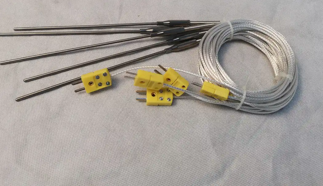
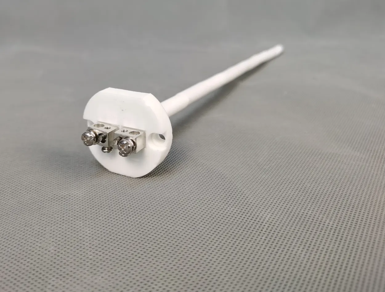
Metal sheaths support compact and flexible probe arrangements, while ceramic protection tubes can isolate the sensing assembly in qualified high-temperature furnace locations. Material compatibility depends on temperature, atmosphere, contamination, thermal shock, mechanical loading and the mounting seal. Describe every gas and process material that can contact the hot-end assembly.
Coordinate mounting, head, plug and cable routing
Specify the thread, compression fitting, flange or other mounting interface together with the available cold-side envelope. Include head orientation, plug access, cable length, minimum bend space and nearby hot surfaces. A mechanically compatible probe can still create service or signal problems if the connector and cable cannot be routed safely.
Confirm the complete electrical connection
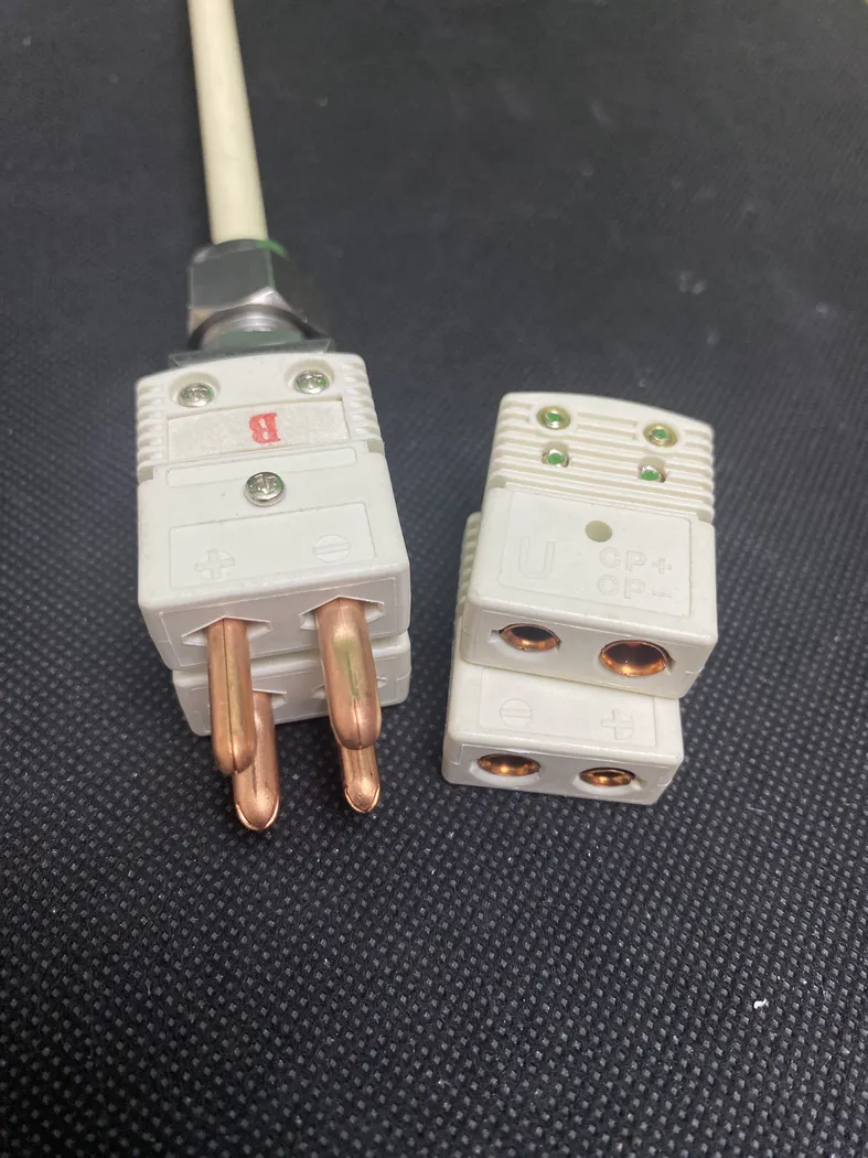
Record the thermocouple type, polarity, number of sensing circuits, connector style, extension or compensating cable and controller input. Mixed connector types, reversed polarity or unsuitable cable can invalidate the measurement even when the probe itself is correct. State whether a single element, dual element, separate safety circuit or transmitter is required.
Prepare evidence for a replacement thermocouple
Photograph the installed sensor before removal, then record the complete assembly beside a scale. Measure the sheath or protection-tube diameter, insertion length, overall length, mounting thread or flange, head or plug dimensions and cable length. Add the furnace model only as context; the dimensioned assembly, wiring and process conditions are the controlling evidence.
Plan calibration, inspection and replacement access
State the required measurement confidence, calibration or verification method and maintenance interval. The installation should allow the sensor to be inspected or replaced without damaging the chamber, process tube, seal or wiring. For critical duties, identify how drift, open-circuit response and an implausible reading must be handled by the control system.
Information required for a thermocouple RFQ
- Measurement purpose: control, safety, load or process evidence
- Normal working temperature and complete thermal cycle
- Gas, pressure, contamination and process-material exposure
- Requested thermocouple type or current sensor information
- Sheath or protection-tube material and diameter
- Insertion length, overall length and sensing position
- Mounting thread, flange, compression fitting or support detail
- Head, plug, cable, polarity and controller connection
- Single or dual sensing circuit, quantity and destination country
For the surrounding heated assembly, review Furnace Chambers. For complete process equipment, compare Industrial Furnaces. Existing furnace renewal can also be discussed through Furnace Retrofit & Replacement Chambers.