
Build a connection map before selecting individual parts
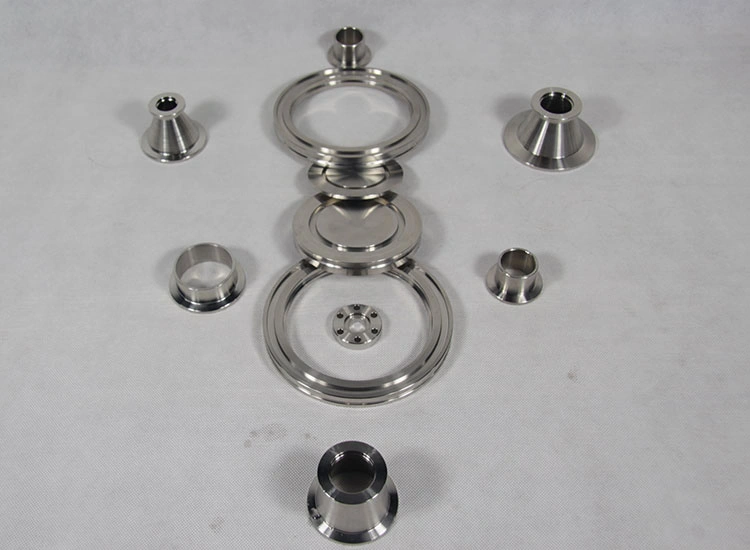
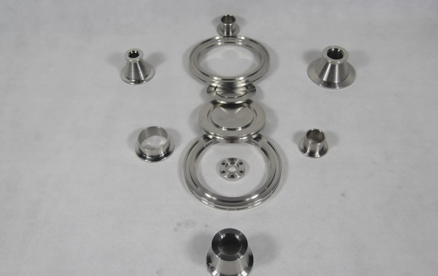
Vacuum flanges and fittings form a connected process boundary between the furnace tube or vessel, gas inlet, pressure measurement, isolation valves, pump and exhaust. A component that looks similar may use a different mating standard, seal or bore. Pyrocore therefore reviews the complete connection chain before qualifying an individual flange, adaptor or replacement part.
Identify each mating standard and size
Record the interface family and nominal size at both ends of every component. KF, ISO, CF and project-specific furnace connections are not automatically interchangeable. Provide face photographs, outside dimensions, bore and the clamp or bolt arrangement. When the standard is unknown, a dimensioned sketch is more reliable than a product nickname.
Start from the furnace tube or vessel connection
Provide the process-tube material, outside diameter, inside diameter, wall thickness, total length and end condition. For a vessel port, record the mating face, bore, orientation and available support. The adaptor must maintain alignment without transferring unacceptable load to a brittle process tube or hot furnace interface.
Select the seal from temperature and process exposure
The seal location can experience a different temperature from the furnace hot zone. State the expected temperature at the flange, gas species, pressure cycle, contamination limit and cleaning method. Elastomer, polymer and metal sealing routes have different boundaries; final material selection is confirmed for the complete configured system.
Coordinate clamps, centering parts and fasteners
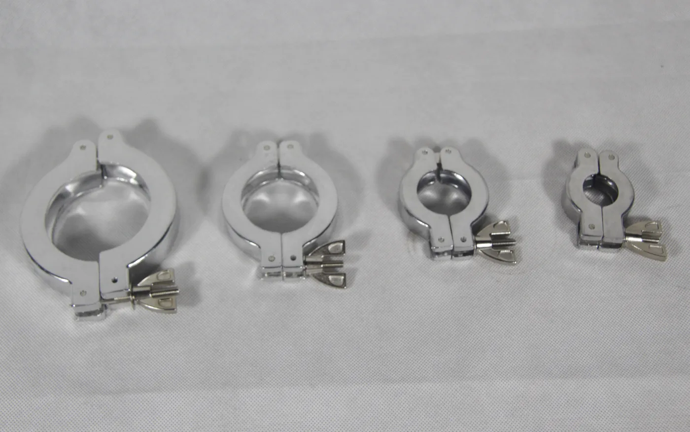
A clamped connection requires the correct mating faces, centering or sealing part and clamp size. A bolted connection requires the matching face geometry, hole pattern, fasteners and tightening access. Include the available radial envelope so the assembly can be installed and serviced beside the furnace enclosure, supports and insulation.
Use reducers and adaptors without creating an unintended restriction
Map the bore through each reducer, elbow, tee, valve and adaptor. The smallest section, internal step, length and orientation can influence conductance, purge flow, particle trapping and cleaning access. State whether the route is used for pumping, gas delivery, pressure measurement, sampling or exhaust so the connection can be reviewed in context.
Position gauges, valves and pump connections deliberately
Pressure measurement should represent the required process location and remain within the gauge operating boundary. Isolation, vent and gas-control valves must be arranged around the intended operating sequence. Provide the pump inlet standard, hose or pipe route, exhaust destination and the required support so the flange is not used as a structural hanger.
Prepare evidence for an unknown replacement fitting
Photograph both mating faces, the installed orientation and the complete connected assembly. Record outside diameter, bore, face depth, bolt circle or clamp geometry, tube dimensions and overall length. Include every loose seal, centering ring, clamp and fastener. Do not discard damaged or worn parts until the replacement connection has been checked against the surrounding equipment.
Confirm assembly, leak checking and service access
Define the cleaning, assembly and leak-check procedure required by the process. Sealing faces should be protected during handling, and tube supports should be aligned before final tightening. If the assembly is opened regularly, state the access and replacement expectations so serviceable seals, clamps and valves can be included in the supply boundary.
Information required for a vacuum flange and fitting RFQ
- Connection drawing from furnace tube or vessel to pump and exhaust
- Flange family and nominal size at every mating interface
- Tube material, outside and inside diameters, wall and end condition
- Gas species, pressure objective and operating sequence
- Temperature expected at each seal location
- Seal, centering, clamp, bolt and fastener requirements
- Bore, reducer, adaptor, valve and gauge arrangement
- Pump inlet, exhaust route, supports and installation clearance
- Cleaning, leak-check, quantity and destination requirements
For a complete heated and sealed assembly, review Vacuum & Atmosphere Tube Furnaces, CVD Tube Furnace Systems and PECVD Tube Furnace Systems.