
Use a fixed vertical process axis when orientation is part of the process
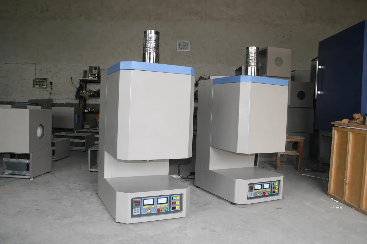
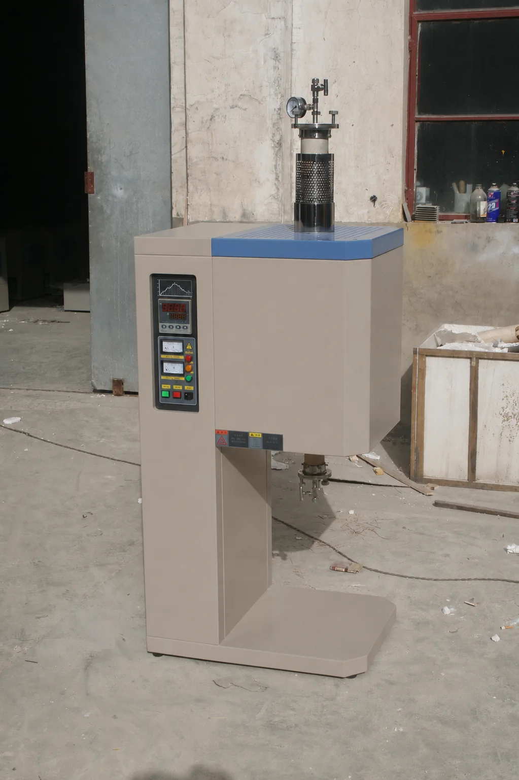
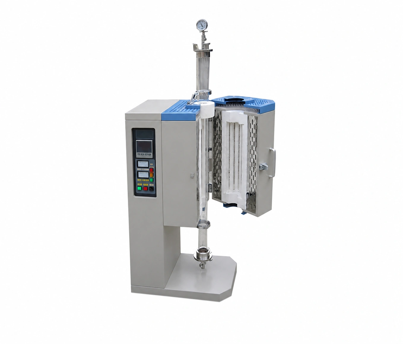
A vertical tube furnace holds the process tube on a top-to-bottom axis through the heated enclosure. This arrangement can support applications where gravity, vertical gas flow, sample suspension, feed or collection position, or available floor space makes a horizontal tube unsuitable. The furnace is specified as a complete vertical assembly: tube, supports, heated section, top and bottom connections, sample position, controls and service envelope.
Confirm why the process must be vertical
Describe the reason for the orientation before selecting the enclosure. A fixed vertical system may be appropriate when a specimen hangs through the heated region, powder or granules move downward, condensate or by-products must be managed above or below the hot zone, or gas should travel in a defined vertical direction. State whether material remains stationary, is inserted and withdrawn, is suspended from an upper support, or passes through the tube.
Map every position along the tube axis
Provide a simple axial drawing from the upper connection to the lower connection. Mark the total tube length, furnace position, heated and usable lengths, sample or material region, insulation plugs, thermocouples, seals, flanges, valves, gauges, feed points, collection points and service clearances. This drawing prevents a nominal heated length from being confused with the usable process region.
Select the process tube as a structural and process component
Tube material, outside diameter, wall thickness and length must suit the temperature cycle, process chemistry, pressure condition and vertical support method. The vertical arrangement can introduce weight and connection loads that differ from a horizontal installation. Identify which end carries the tube or attached hardware, how thermal expansion is accommodated and whether external piping or vessels can impose bending or axial load.
Choose between a closed and split heating enclosure
A closed enclosure can suit a tube that is installed through the furnace during assembly. A split or opening enclosure can provide direct access around an existing tube and simplify inspection or process setup. For an opening design, confirm the hinge direction, door swing, fastening method, hot-surface boundary, tube clearance and the conditions under which the enclosure may be opened. Split construction changes access; it does not remove the need for controlled support and safe isolation.
Define top and bottom connections independently
The two tube ends may perform different jobs. One end may carry a sample suspension, feed device, gas inlet, gauge or viewing interface while the other provides collection, pumping, exhaust or drainage. List each connection, mating standard, bore, material, seal, valve, instrument and supported mass. Also state the direction of gas flow and the intended destination of process exhaust or by-products.
Place the sample and temperature evidence deliberately
State the exact position and length of the workpiece, specimen, powder bed or reaction region relative to the heated enclosure. Furnace-controller temperature is not automatically the same as sample temperature. Define whether the process requires only furnace control, an additional thermocouple near the load, a movable sensor, profile qualification or recorded data. Sensor insertion and lead routing must remain compatible with the vertical tube, seals and material path.
Coordinate atmosphere control with gravity and by-products
For controlled gas or reduced pressure, provide gas species, purity objective, inlet position, flow direction, operating-pressure objective, pumping path, purge and backfill sequence, exhaust destination and any known condensable, corrosive or particulate by-products. Their expected movement through a vertical system affects filters, traps, collection vessels, valves and cleaning access. The complete configured boundary determines atmosphere and pressure performance.
Plan sample loading, feed and collection before finalizing height
Explain how the material enters and leaves the system and whether loading occurs from the top, bottom or through a removable tube assembly. Include carriers, boats, baskets, suspension rods, feed hoppers, collection containers and lifting tools in the dimensional review. Total equipment height must include the furnace body, tube extensions, connection hardware, operating travel, lifting clearance and safe access for installation and removal.
Separate a fixed vertical furnace from an adjustable-angle furnace
Select this route when the process axis is intended to remain vertical and the support, connections and operating sequence are designed around that orientation. Use an Adjustable-Angle Tube Furnace when the process needs a pivoting enclosure or more than one qualified operating position. If several independently controlled sections are required along the axis, review Multi-Zone Tube Furnaces as part of the same specification.
Design the installation and service envelope
Provide the available floor area, ceiling height, access route and utilities. Allow working space around upper and lower flanges, valves, gauges, tube supports, enclosure doors, heating terminals, thermocouples and control equipment. Identify any external frame, wall support, platform or lifting equipment. Service access should permit removal of the tube and heating enclosure without transferring unintended load to fragile process components.
Information required for a vertical tube furnace RFQ
- Material, process objective and reason for vertical orientation
- Process-tube material, outside diameter, wall thickness and total length
- Dimensioned axial drawing with heated region and sample or material positions
- Working temperature and complete heating, holding and cooling cycle
- Stationary, suspended, inserted, fed or through-flow material arrangement
- Upper and lower connection, flange, support and instrument details
- Gas species, flow direction, pressure objective, exhaust and by-products
- Closed or split enclosure preference and required access method
- Temperature measurement, control zones and data-recording requirements
- Available floor area, ceiling height, loading access and service clearances
- Power supply, utilities, destination and installation scope
For a general stationary horizontal route, start with Tube Furnaces. Controlled gas or pumping hardware can be coordinated through Vacuum & Atmosphere Tube Furnaces and Vacuum Flanges & Fittings. A replacement heated section can begin with Tube Furnace Chambers.