
Test the complete heat-treatment sequence
A heat treatment process testing furnace is used when the engineering question extends beyond heating a specimen. The system can coordinate specimen loading, a programmed thermal cycle, observation, controlled movement from the heated zone and a defined cooling or quench step. Selection begins with the material and sequence that must be reproduced, not with a maximum-temperature label.
Build the equipment around specimen movement
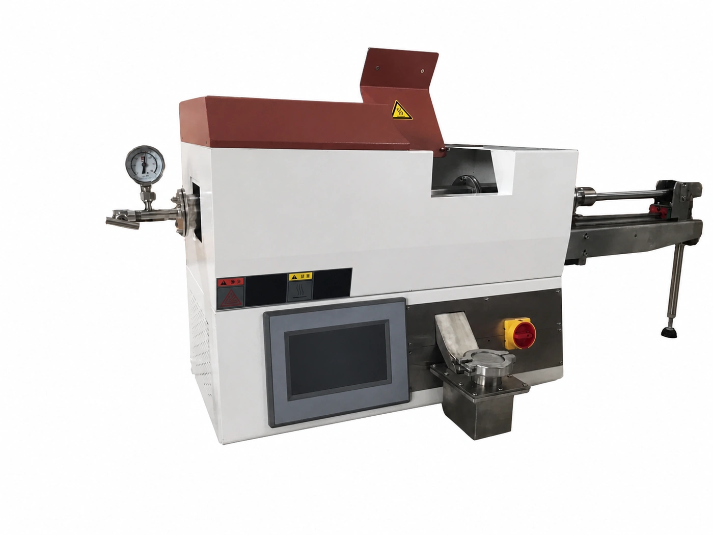
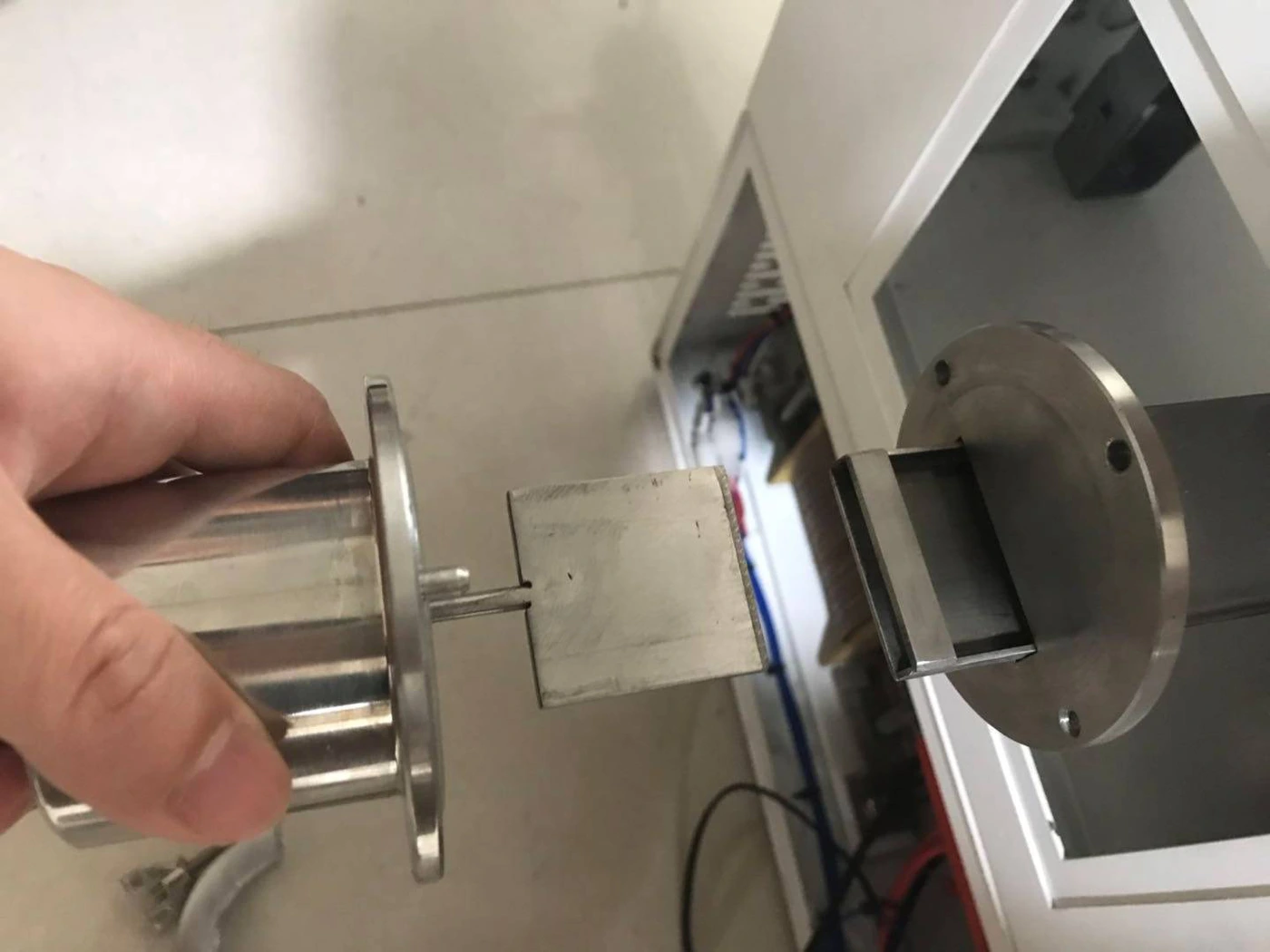
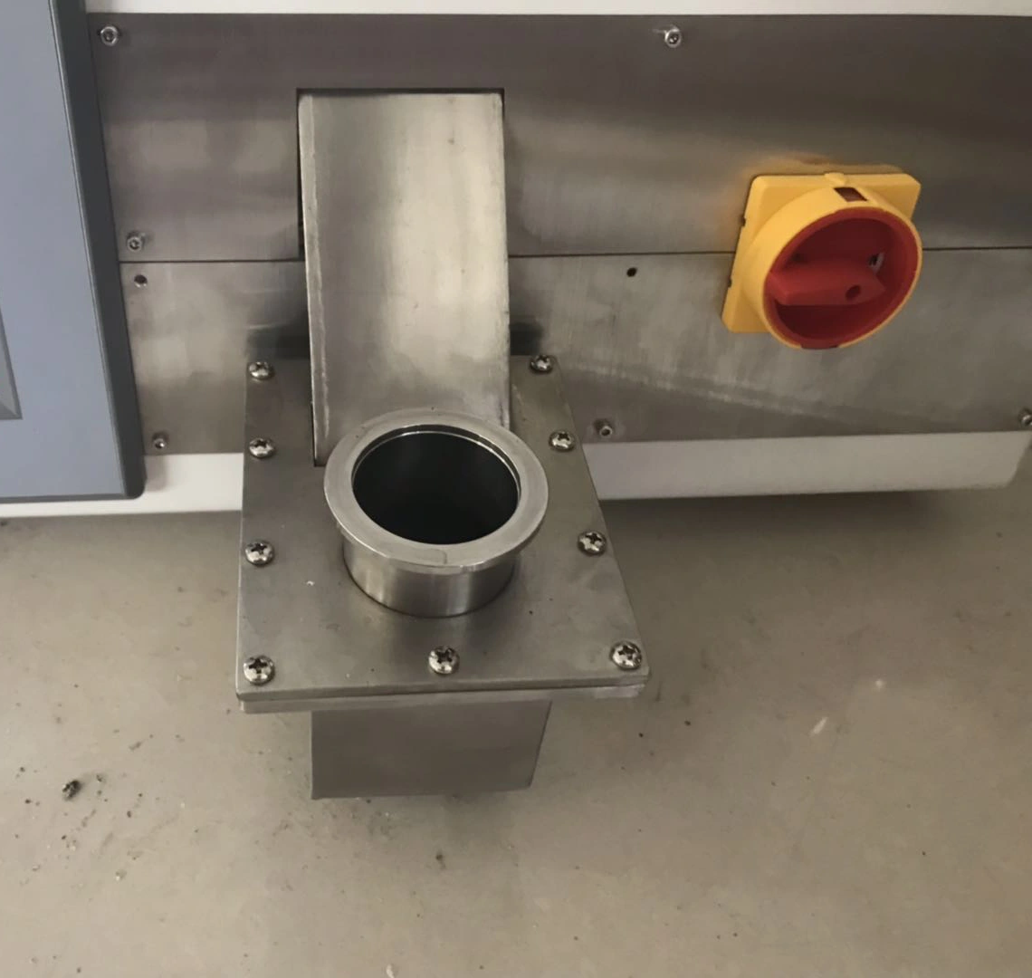
The illustrated configuration combines a heated enclosure with a specimen-loading interface, observation port, linear transfer assembly and separate quench vessel. The useful specimen envelope is determined by the carrier and clear transfer path as well as by the heated zone. Send the specimen and carrier drawing, insertion direction, required stroke, clearance and preferred loading method.
Define the environment through every process stage
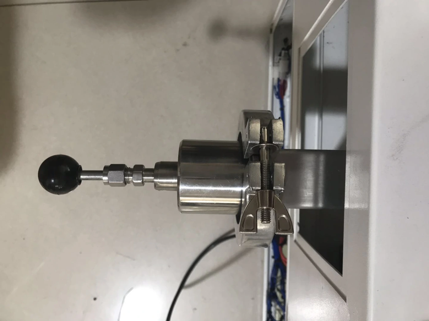
State the initial condition, evacuation or purge stages, process gas, operating pressure or flow objective, heating condition, transfer condition, cooling environment and final opening procedure. A controlled atmosphere in the heated zone does not automatically establish the same environment through transfer or quenching. The sealing and gas boundary must be qualified against the requested sequence.
Observation is an engineering interface
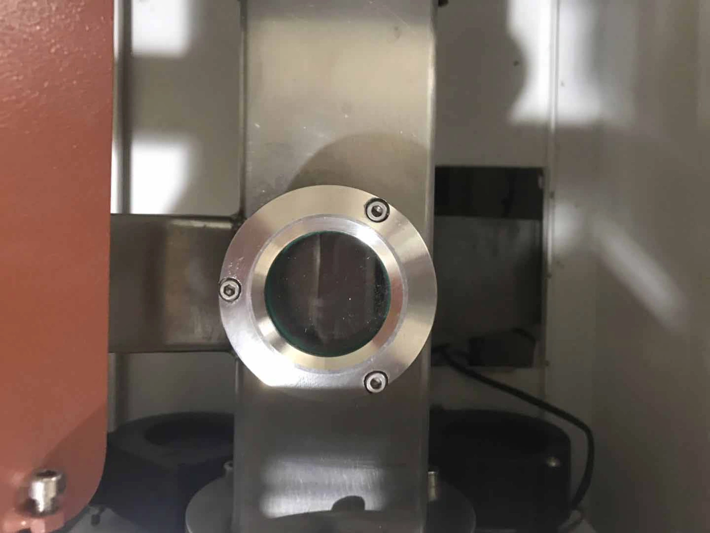
Describe what must be observed, at which stage, and whether the view is used for timing, movement confirmation or another process decision. Window material, location, field of view, temperature exposure and protection from deposits or splash depend on the process. Observation does not replace temperature or position measurement where measurable evidence is required.
Coordinate transfer timing and repeatability
Provide the desired time relationship between the end of heating, specimen movement and entry into the cooling medium. State whether movement is manual, assisted or automatically sequenced, and identify the variables that must be controlled or recorded. The transfer rail, carrier, seals, travel stops and quench position are selected together.
Specify the cooling or quench boundary
Identify the medium, normal volume, starting condition, agitation or circulation requirement, specimen load, contamination controls and safe handling route. Oil, water and other media create different fire, vapour, splash, corrosion and waste-management considerations. Final equipment and facility safeguards follow the selected material and quench procedure.
Controls, records and interlocks
List recipe stages, temperature channels, specimen-position signals, transfer commands, pressure or gas measurements, alarms, interlocks and data-export requirements. Define the safe response to insufficient gas, loss of cooling, an open interface, an incomplete transfer or a power interruption. Control functions are confirmed for the selected configuration.
Acceptance based on the intended test
Acceptance may include dimensional and functional checks, sensor verification, empty and loaded cycle evidence, transfer repeatability, atmosphere checks and a defined specimen trial. State the required report, sample preparation, hardness or other downstream test method, and the conditions that establish a successful equipment trial.
Information required for a process testing furnace RFQ
- Material, specimen drawing, carrier and available safety information
- Complete heating, holding, transfer, cooling and opening sequence
- Working temperature and required measurement positions
- Air, vacuum or gas condition at each process stage
- Observation objective, field of view and window-protection concerns
- Transfer direction, stroke, timing and manual or automatic operating preference
- Cooling or quench medium, vessel, handling and facility safeguards
- Controls, records, interlocks and measurable acceptance method
- Power, gas, pumping, cooling, exhaust, footprint and destination
Review the Heat Treatment Process Development & Testing application and use the specification guide to prepare the RFQ. For a stationary sealed batch route without integrated transfer and quench handling, compare Vacuum & Atmosphere Box Furnaces.