
Define the required environment throughout the complete cycle
Vacuum and controlled-atmosphere heat treatment is specified from the material, load and process sequence. The environment needed during heating may differ from the condition required for holding, cooling or unloading. A useful inquiry therefore describes evacuation, purge, gas admission, pressure changes, heating, cooling, backfill and safe opening as one connected cycle.
Explain why air operation is unsuitable
State the mechanism that must be controlled: oxidation, decarburization, moisture, contamination, volatilization, reaction with a selected gas or another documented concern. Identify acceptable and unacceptable exposure conditions. This information guides whether an inert flow, reactive atmosphere, purge sequence, reduced-pressure process or combined route should be evaluated.
Describe the material, fixture and contamination boundary
Provide workpiece material, dimensions, mass, surface condition and batch arrangement. Include trays, boats, baskets, setters, supports, thermocouples and fixture materials. Identify oils, binders, cleaning residues, coatings or process by-products that may add gas load or contaminate the hot zone, seals, pump or future batches.
Write the pressure and gas sequence step by step
List the starting condition, evacuation objective, purge cycles, process gases, flow or pressure condition, hold stages, cooling atmosphere, backfill and final venting. Include gas purity objectives, available supply pressure and exhaust destination. Achievable pressure and atmosphere quality depend on the complete configured assembly and operating state, not on a pump label alone.
Choose a tube or sealed batch route
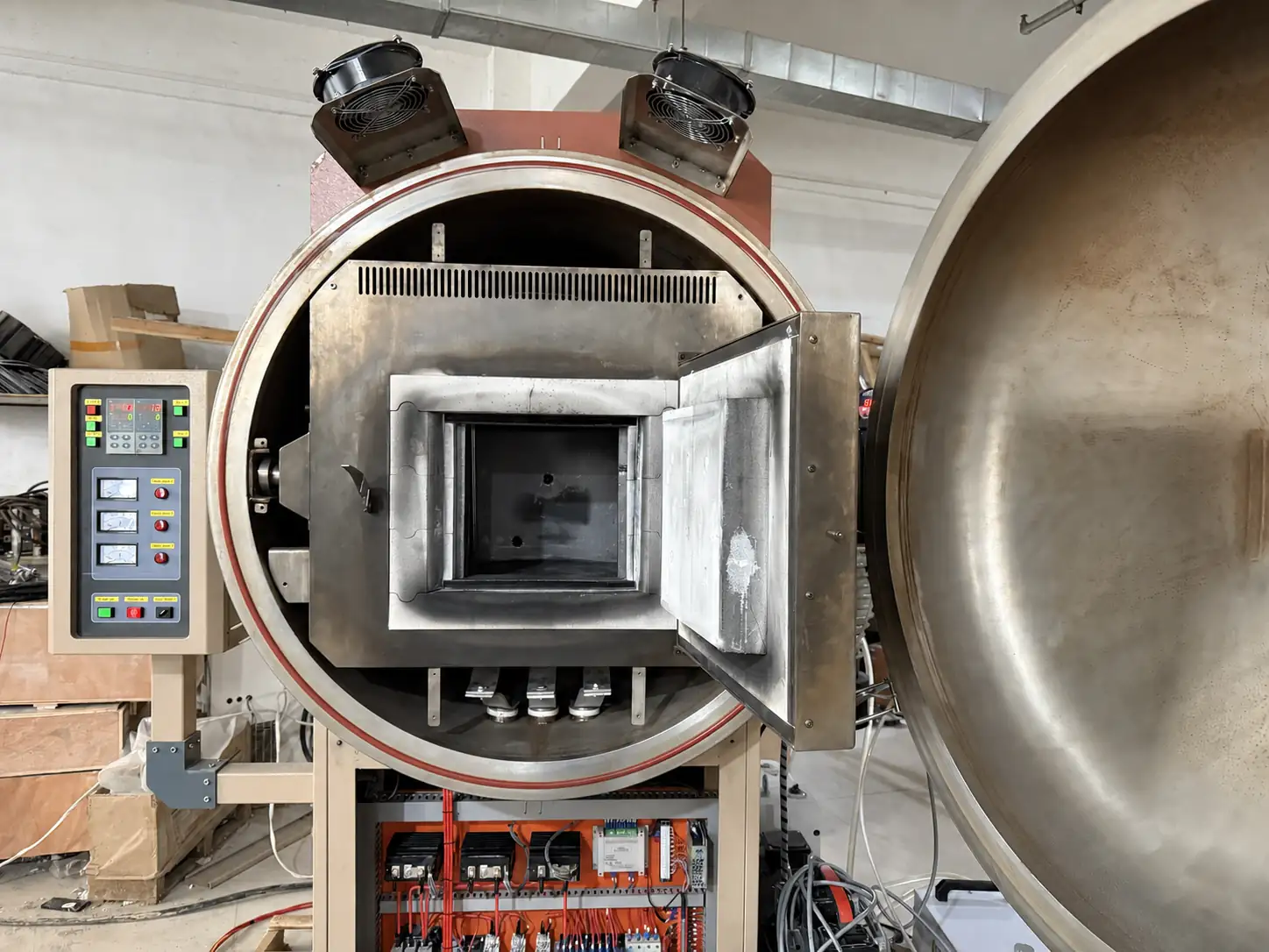
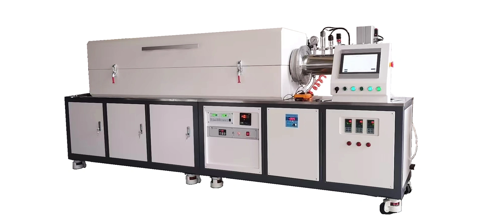
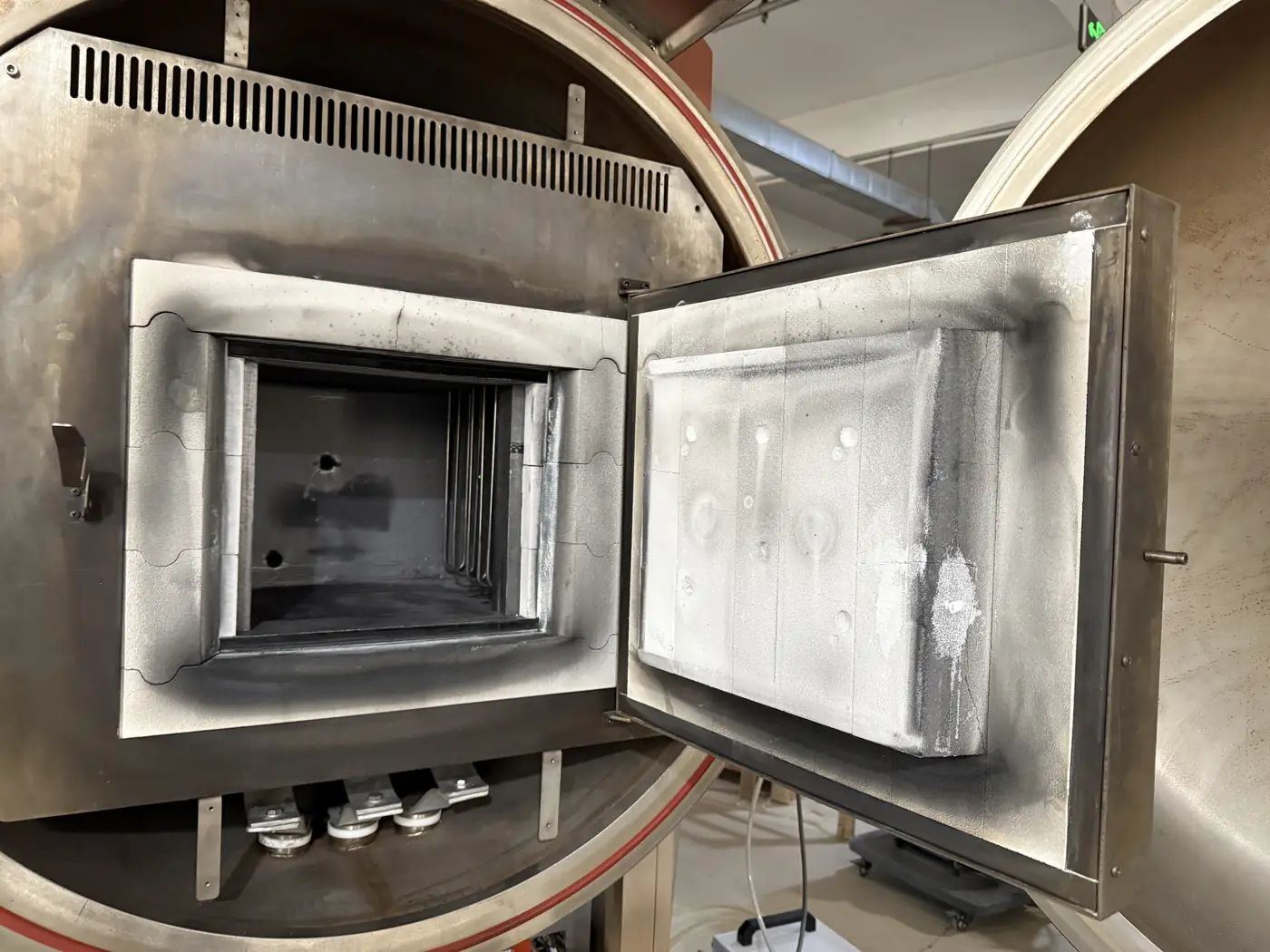
Vacuum & Atmosphere Tube Furnaces fit samples or material paths that can be contained within a process tube and accessed through defined end interfaces. Vacuum & Atmosphere Box Furnaces provide an enclosed batch chamber inside a sealed vessel for larger or differently shaped loads. The decision follows from load geometry, usable space, sealing, atmosphere, handling and cooling requirements.
Distinguish usable hot space from vessel size
Dimension the real load with fixtures and required clearance from chamber walls, elements, radiation shields, sensors, tube ends and doors. The vessel or outer enclosure also needs room for insulation, feedthroughs, supports and cooling. Provide the loading route, maximum component mass and any lifting or transfer equipment.
Coordinate pumping, gas delivery and exhaust
Define which pumps, valves, gauges, flow controls, regulators, filters, traps, backfill components and exhaust-treatment equipment are expected within the supply boundary. Identify gases and by-products that may be corrosive, combustible, toxic, condensable or particulate. Materials compatibility and facility ventilation must be reviewed before the process train is finalized.
Control heating and cooling around the load
Provide working temperature, ramp, hold and required cooling endpoint. State whether cooling occurs under vacuum, flowing gas, static gas or another qualified condition. Furnace sensors control from defined positions; if the workpiece temperature or batch profile is critical, specify load thermocouples, profile testing or another acceptance method.
Protect seals, instruments and process interfaces
Door and tube seals, feedthroughs, gauges, valves and pumps have temperature and contamination limits. Hot-zone end losses, radiation, vapours and thermal expansion can affect these interfaces. Cooling, shielding, isolation and service access are selected for the actual arrangement rather than copied from an unrelated system.
Define interlocks and permitted process states
State the allowed relationship among door or flange closure, pressure, gas flow, heating, cooling and venting. Pressure measurement, cooling flow, over-temperature protection, gas alarms and pump status may form part of the interlock strategy. Site risk assessment and facility responsibilities remain part of the final engineering review.
Specify records and acceptance evidence
Identify which temperatures, pressures, flows, valve states, alarms or cycle steps must be displayed, recorded or exported. Define calibration or verification expectations and the acceptable response to an interrupted cycle. Material results are qualified from the agreed process and evidence; they are not promised by equipment appearance.
Information required for a vacuum or atmosphere heat-treatment inquiry
- Material, surface condition, process objective and available safety information
- Part and fixture drawings, batch arrangement and total mass
- Working temperature and complete heating, holding and cooling cycle
- Reason air operation is unsuitable and acceptable exposure limits
- Evacuation, purge, process-gas, pressure, flow, cooling and venting sequence
- Gas purity, supply conditions, by-products and exhaust destination
- Required usable chamber or tube dimensions and loading route
- Pump, valve, gauge, flow-control, trap and gas-train supply boundary
- Load-temperature, pressure, flow, data and acceptance requirements
- Power, cooling water, gases, ventilation, installation space and destination
Compatible connection hardware can be reviewed through Vacuum Flanges & Fittings, while application-specific sensing begins with Industrial Furnace Thermocouples.