
Use multiple zones to shape the temperature profile
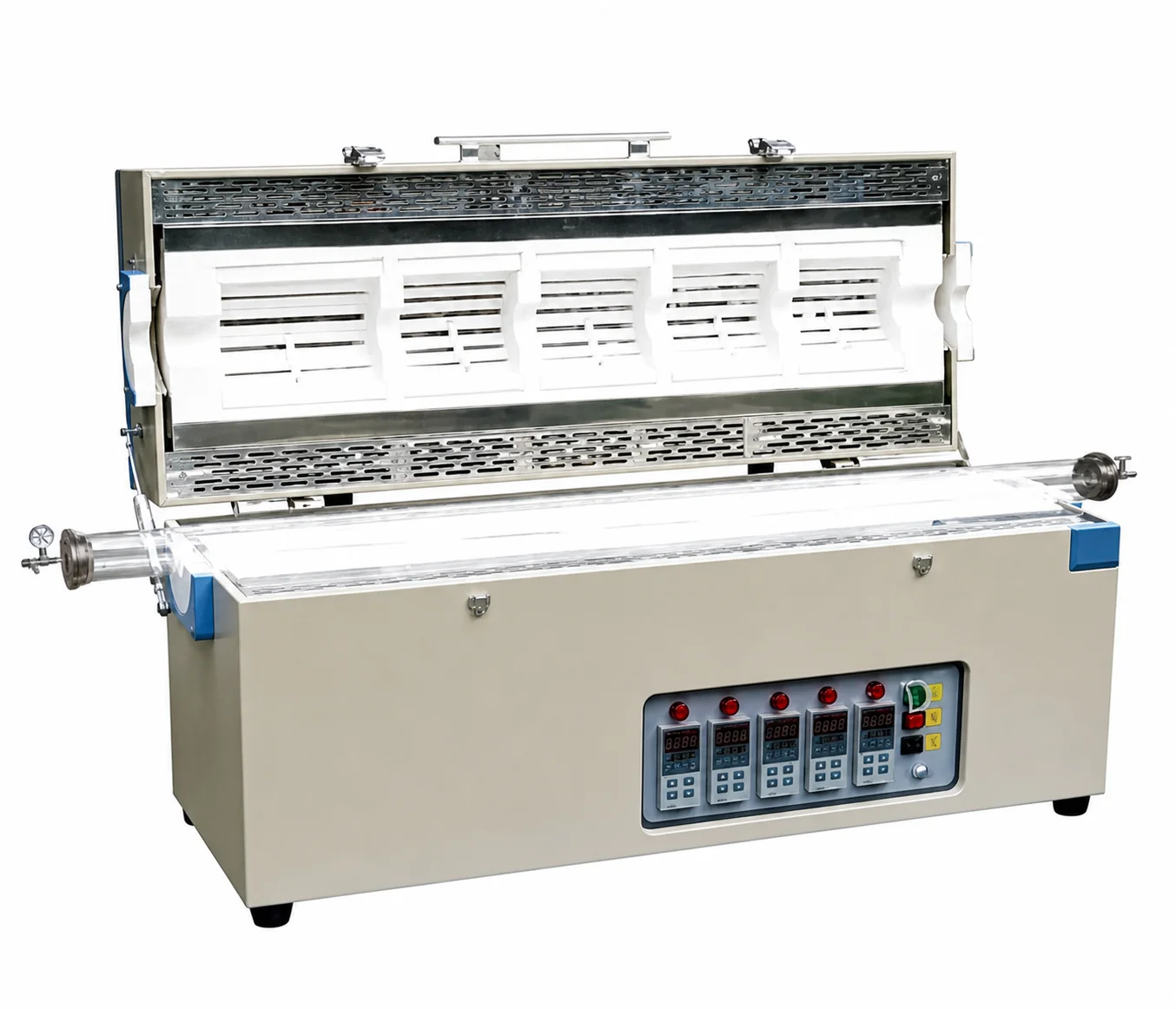
A multi-zone tube furnace divides the heated length into independently controlled sections. The purpose may be to extend a working region, create an axial temperature gradient or place different process stages along one tube. The correct arrangement begins with the required sample positions and thermal sequence, not simply the number of controllers on the cabinet.
Define the thermal objective before selecting zone count
Two, three, five or project-specific zone arrangements can support different process layouts. More zones do not automatically produce better results. State where the load sits, which sections must be controlled independently and whether the target is a longer working region or a deliberate temperature change along the tube.
Map each sample position to the heated length
Provide a simple axial drawing showing the tube ends, seals, furnace centreline, each sample or substrate position and the required thermal sections. Include boats, fixtures, plugs and thermocouples. Adjacent zones interact thermally, so the final profile depends on zone length, insulation joints, tube material, load and setpoint relationship.
Choose horizontal or vertical orientation from the process
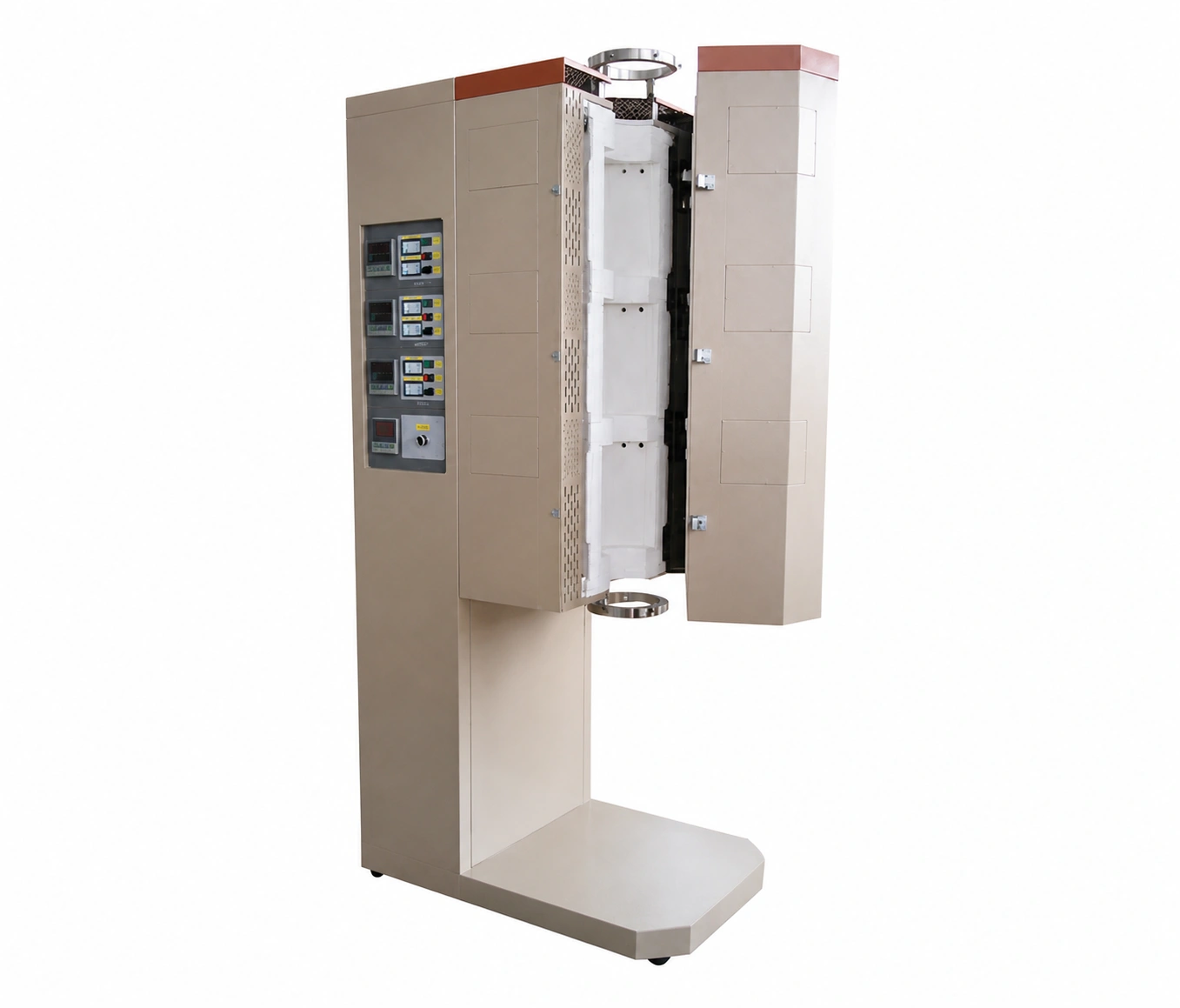
Horizontal systems suit many boat, powder and gas-flow arrangements. A vertical configuration may support gravity-assisted loading, suspended samples or another process-specific orientation. State the required movement, support method and access direction. Orientation also affects flange support, hot surfaces, tube loading and the surrounding equipment envelope.
Specify the process tube and atmosphere boundary
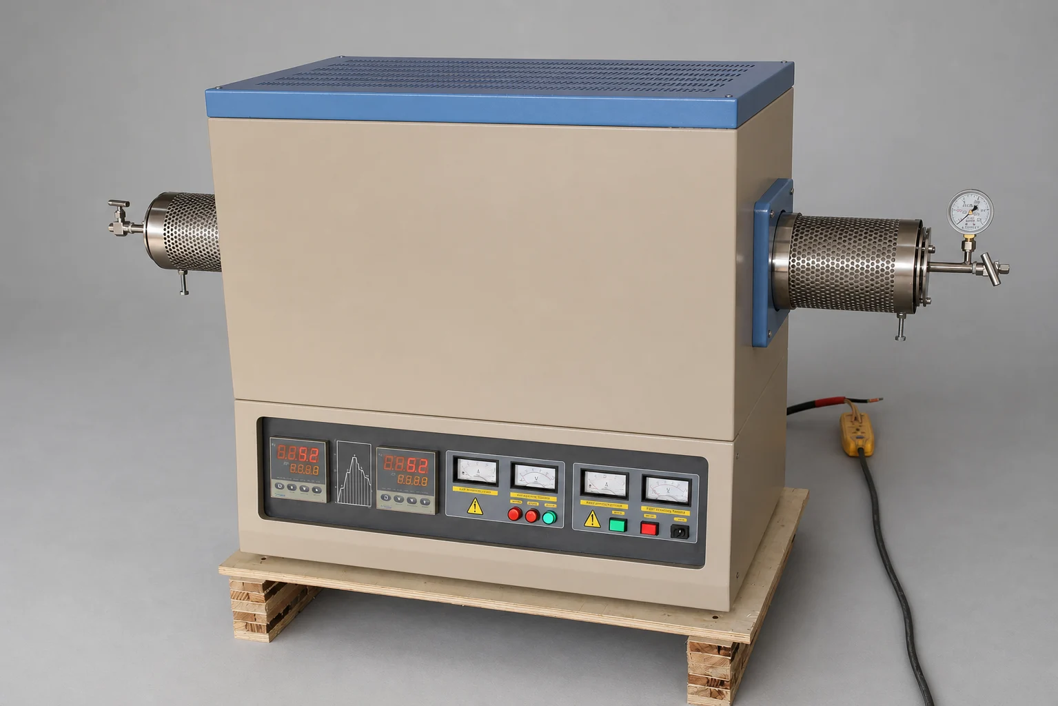
The furnace enclosure does not by itself contain vacuum or process gas. Define the tube material, outside and inside diameters, total length, end-seal design, gas inlet, exhaust, vacuum connection and feedthrough requirements. Process temperature, pressure and chemical compatibility must be reviewed for the complete tube-and-seal system.
Coordinate independent control and sensing
Describe whether each zone follows an independent recipe, a shared cycle with offset setpoints or a coordinated gradient. Identify the sensor type and location for every controlled section. If the process requires proof of a temperature profile, define the measurement positions, load condition and acceptance method rather than assuming controller display values represent the sample.
Split construction and service access
An opening or split furnace body can simplify process-tube installation and service. The hinge direction, opening clearance, hot-surface protection, tube supports and safe access must fit the laboratory or production layout. Fixed and split configurations should be selected around the actual tube-change and maintenance workflow.
Information required for a multi-zone tube furnace RFQ
- Process objective and material
- Required zone count or axial temperature profile
- Zone and sample positions on a dimensioned sketch
- Working cycle and independent setpoint requirements
- Process-tube material, diameter and length
- Atmosphere, vacuum, gas-flow and exhaust boundary
- Horizontal or vertical orientation and loading method
- Sensor, data-recording, controls and interlock requirements
- Power supply, destination and documentation needs
Use the Multi-Zone Tube Furnace Specification Guide to prepare the drawing and process information. For a single heated section, review Tube Furnaces. For integrated gas and vacuum equipment, see Vacuum & Atmosphere Tube Furnaces.