
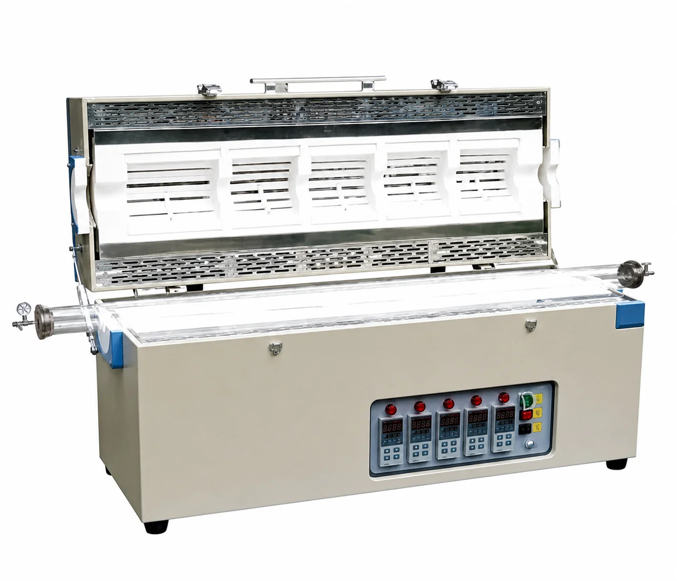
Start with a one-line process objective
Describe what must happen along the process tube: maintain a longer working region, create an axial gradient, heat separate sample positions or coordinate consecutive process stages. This sentence determines whether multiple zones are useful and what information the furnace supplier must qualify.
1. Draw the tube and every process position
Create a side-view sketch with one dimension line. Mark the process-tube length and diameter, furnace centreline, desired heated sections, sample or substrate positions, boats, plugs, feedthroughs and end seals. Do not describe a long uniform region using only the external furnace width.
2. State the required temperature relationship
For every section, state the intended working setpoint or relationship to the adjacent zone, the ramp and hold sequence and whether the zones operate simultaneously. If the exact profile is not yet known, provide the process objective and clearly identify it as a development requirement.
3. Separate control accuracy from sample evidence
A controller regulates from its sensor position. The sample can experience a different temperature because of tube material, load mass, gas flow, fixtures and distance from the sensor. Specify whether controller regulation is sufficient or whether a loaded temperature-profile survey, additional thermocouples or data recording is required.
4. Define the tube before the flanges
State the tube material, outside diameter, inside diameter, length, allowable process condition and expected replacement method. Then define flange type, gas inlet, exhaust, vacuum connection, pressure measurement and feedthroughs. The permitted atmosphere and pressure depend on the complete assembly, not the furnace cabinet alone.
5. Choose orientation and opening method
Identify horizontal or vertical operation, how the load enters the tube and how the tube is supported. For split furnaces, show hinge direction and opening clearance. For vertical systems, describe suspended loads, gravity movement and the support required above and below the heated section.
6. Define controls and safety functions
List independent zone recipes, synchronized steps, alarms, over-temperature protection, interlocks, data logging and communication requirements. Also identify what other equipment must be coordinated, such as gas delivery, vacuum pumps, exhaust treatment or process instrumentation.
7. Send an RFQ package that can be reviewed
- One-line process objective
- Dimensioned axial tube and zone sketch
- Material, load, fixture and sample positions
- Working temperature relationship and complete cycle
- Tube, seals, gas, vacuum and exhaust requirements
- Orientation, opening and maintenance access
- Control, monitoring, data and acceptance needs
- Utilities, power supply, destination and documentation requirements
Discuss the equipment configuration on the Multi-Zone Tube Furnaces page. For broader tube-furnace selection, use How to Specify a Tube Furnace.