
Combine different furnace formats without merging their process boundaries
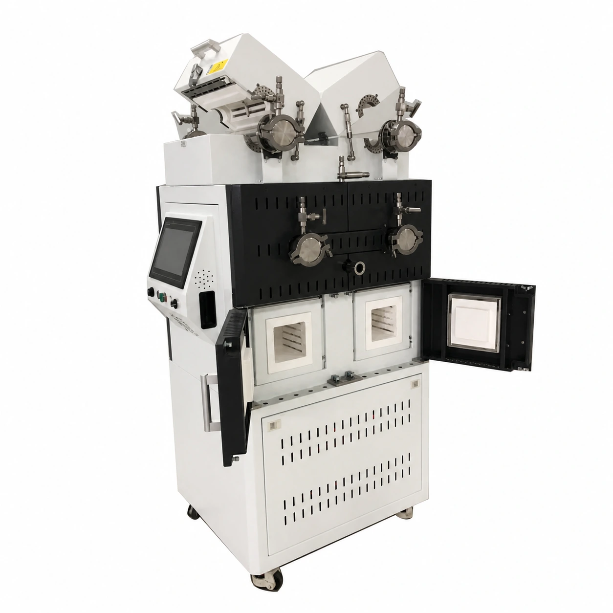
An integrated multi-channel box and tube furnace places several independently controlled thermal workstations in one cabinet. Tube stations can provide process-tube access and controlled-gas or vacuum interfaces, while box stations provide enclosed batch chambers. The platform can reduce duplicated footprint and utility routing when the experiments, station count and simultaneous operating duty are defined clearly.
Define every station before designing the cabinet
Prepare a station schedule rather than one combined furnace description. For each tube station, state the process-tube material, diameter, heated length, load method, flange and atmosphere requirements. For each box station, state usable chamber dimensions, load, fixture, door access and cycle. Identify which stations must operate at the same time.
Independent control requires coordinated electrical design
Individual recipes and controllers do not make the stations electrically independent from the facility. Provide the available voltage, phase, frequency and power limit, together with the expected simultaneous duty. Main isolation, branch protection, heating circuits, sensor inputs, alarms and emergency response are coordinated across the complete cabinet.
Tube stations and process connections
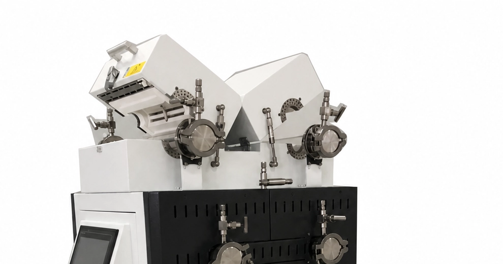
Tube material, outside diameter, seals, flange arrangement, gas inlet, outlet, pumping path and sample access determine each tube channel. State whether tubes must be removed frequently and how hot parts will be supported. A visually similar flange or tube is not interchangeable without dimensional and process review.
Box chambers and loading access
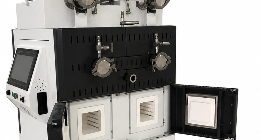
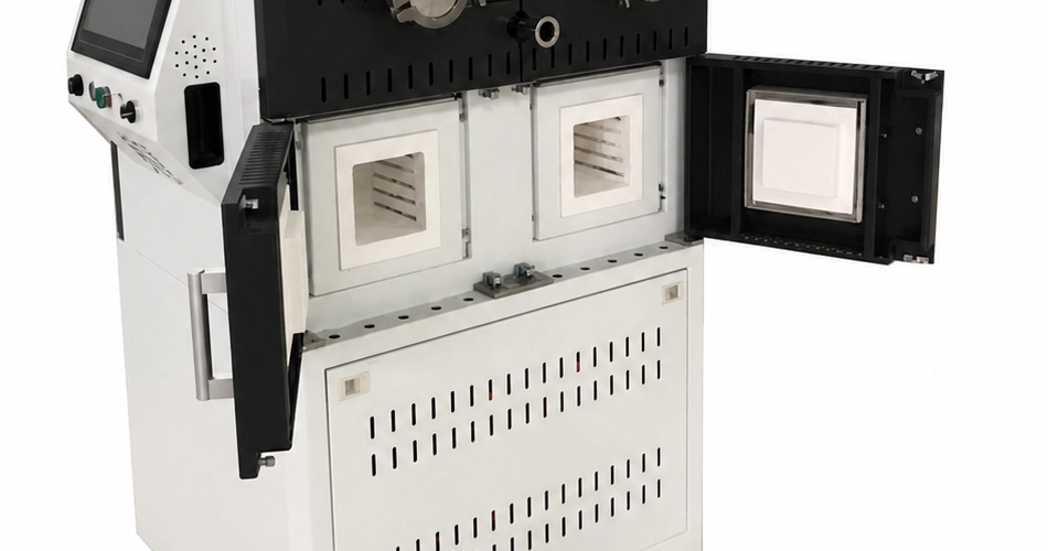
Usable chamber dimensions must include the load, tray or fixture and clearance for heating and handling. Door swing, insulation, hot-face protection and the operator route affect station placement. If front and rear chambers are required, provide aisle and service clearances on both sides of the equipment.
Separate gas, vacuum and exhaust decisions by station
List the gas species, flow direction, pressure objective, pumping requirement and exhaust condition for each channel. Confirm whether any supply, regulator, manifold, pump or exhaust connection may be shared. Isolation, backflow prevention, contamination control and safe venting must be reviewed when multiple stations operate in parallel.
Plan the human workflow
Describe how many operators use the platform, where samples are prepared, which doors or flanges may be opened simultaneously and how hot tools or carriers are stored. The control screen, station labels, access height, viewing position and maintenance panels should support clear identification of the active channel.
Serviceability and future station planning
Provide the expected tube, seal, thermocouple, heating-element and chamber maintenance tasks. The cabinet should allow safe access to branch protection, terminals, controllers, valves and cooling connections without disturbing unrelated stations. Future expansion must be declared before electrical and utility distribution is finalized.
Information required for an integrated furnace RFQ
- Station-by-station process and material schedule
- Tube material, diameter, heated length, seals and end interfaces for each tube station
- Usable box-chamber dimensions, load and door access for each box station
- Working cycle, atmosphere and control program for every station
- Required simultaneous operating combinations and facility power limit
- Gas, vacuum, cooling and exhaust connections, including any proposed shared equipment
- Control, records, alarms, interlocks and station-identification requirements
- Footprint, aisle, room access, service clearance and destination
For tube-only requirements, review Tube Furnaces and the Tube Furnace Specification Guide. For single-chamber batch work, compare Muffle & Box Furnaces. Use the Furnace RFQ Checklist to organize shared facility and commercial information.