
Build the chamber around the tube and axial process region
A diffusion furnace chamber is a long cylindrical heated assembly surrounding a separate process tube. The chamber may use split refractory sections, integrated resistance-heating paths, sensors, terminals and a supporting metal shell. Selection begins with the tube, required heated profile and equipment interface; the chamber alone does not establish the gas, pressure or process result inside the tube.
Define the complete axial drawing before selecting zones
Provide the tube and furnace centerline with the process region, load or wafer positions, heated length, end transitions, insulation extensions, flange locations and support points. Mark the desired relationship between controlled sections. Zone count is an equipment architecture decision; it does not by itself prove the loaded axial temperature profile.
Size bore clearance for operation and service
The chamber bore must accommodate the process tube, expansion, alignment, installation method and any permitted insulation interface. Record the tube outside diameter and tolerance, the required radial clearance and the chamber opening method. Include tube supports, end hardware and the procedure used to install or remove the chamber without loading the tube incorrectly.
Choose split geometry and shell construction together
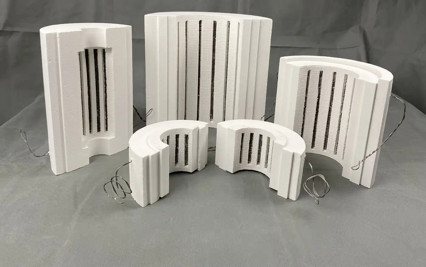
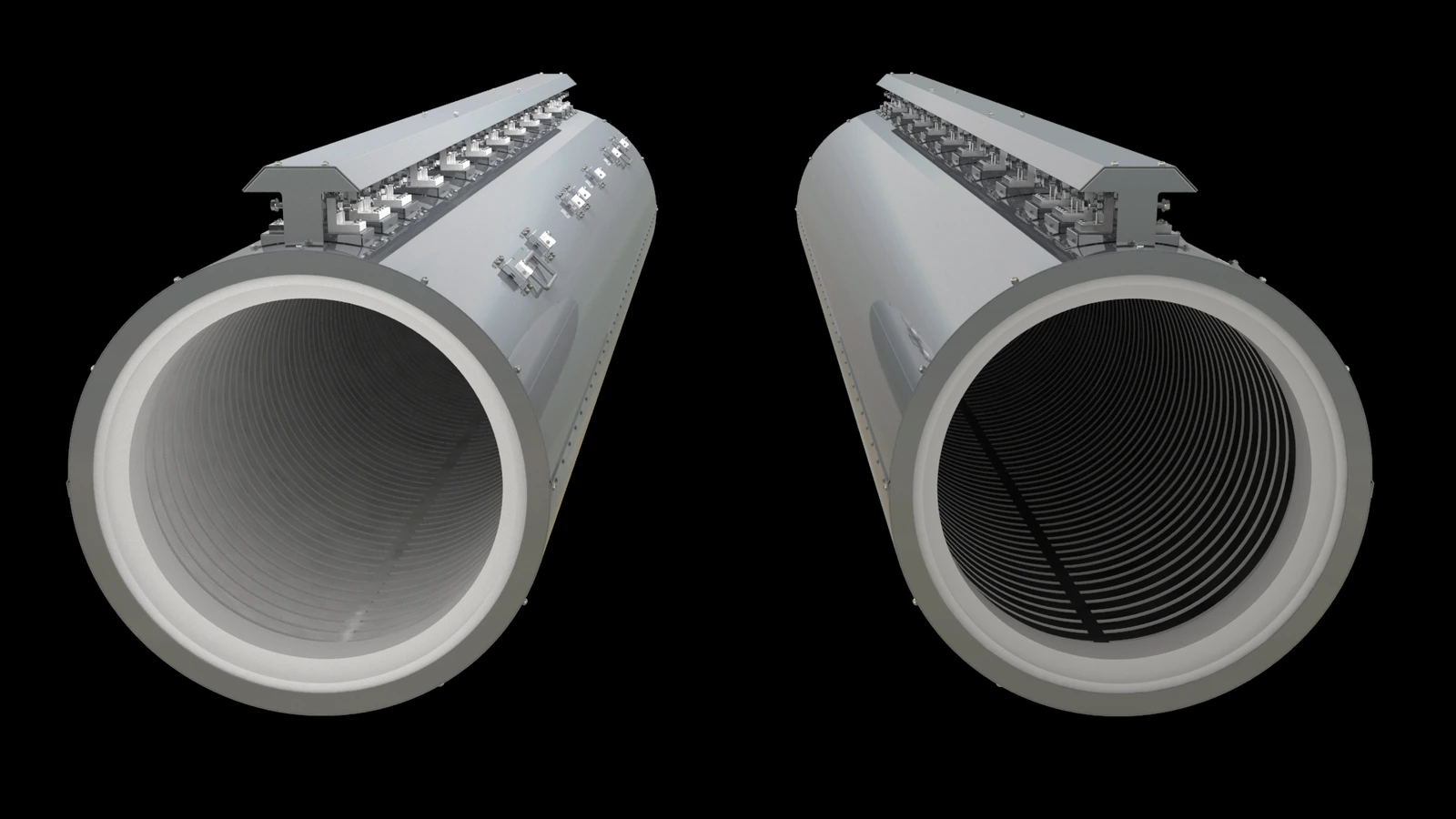
Split chamber sections can support installation, inspection and replacement around a long tube. Define the split orientation, number and length of sections, fastening, hinges or lifting method, outer shell envelope and supporting frame. The illustrated configuration rendering explains a possible shell-and-chamber relationship; final construction is confirmed from the project drawing.
Develop element paths from the required thermal profile
Integrated resistance-heating paths can be arranged within shaped cylindrical sections. Element material, groove pattern, section length, power distribution and insulation depend on the required working cycle, tube geometry and loaded thermal objective. Provide the expected operating sequence and acceptance locations instead of relying only on a maximum furnace rating.
Coordinate zones, sensors and control evidence
For every controlled section, define the purpose, sensor position, controller relationship and alarm or over-temperature boundary. Separate controller readings from process-tube or load evidence. If uniformity, gradient or repeatability must be demonstrated, state the measurement method, locations and operating condition for acceptance.
Plan terminals and service access before finalizing the shell
Terminal groups, lead-outs, junctions and sensor cables require protected routing outside the hot insulation. Provide the local voltage, phase, available power, control architecture and preferred cabinet relationship. Shell panels, covers and support steel must leave practical access for inspection and replacement while maintaining required clearances.
Keep atmosphere and process claims inside the tube boundary
The diffusion chamber supplies heat around the process tube. Tube material, end seals, gas delivery, pressure measurement, pumping, exhaust and process safety establish the controlled environment. Provide these system requirements for compatibility review, but they must not be treated as performance delivered by the chamber alone.
Use replacement evidence when an installed chamber is being renewed
For replacement work, photograph the complete furnace, each chamber section, bore, split line, element path, sensor and terminal group before disassembly. Record section lengths, inner and outer dimensions, shell interfaces, cold resistance and wiring groups where available. A revised chamber can be discussed when the reason for the change and the surrounding system limits are clear.
Information required for a diffusion chamber RFQ
- New OEM system or replacement project
- Process-tube material, dimensions, supports and expansion boundary
- Axial process drawing with sample or load positions
- Total chamber length, bore, heated sections and transition regions
- Split, shell, fastening, mounting and service-access requirements
- Working cycle and required profile or acceptance method
- Voltage, phase, power, element groups, sensors and controls
- Gas, pressure and end-interface context for compatibility review
- Quantity, installation constraints and destination country
For smaller split heated sections, compare Tube Furnace Chambers. For complete multi-section equipment, review Multi-Zone Tube Furnaces and the Multi-Zone Tube Furnace Specification Guide.