
Select the element as part of the furnace system
A heating element cannot be selected safely from temperature alone. The furnace geometry, working cycle, atmosphere, load, element position, electrical circuit, terminals, controller and expected maintenance all affect compatibility. SiC and MoSi₂ are distinct element routes, but final material, shape and electrical values must be qualified for the actual furnace.
1. Separate working temperature from maximum rating
Provide the normal working temperature, ramp, hold, cooling and cycle frequency. A published or historical maximum does not establish suitability for continuous operation, a particular atmosphere or the selected element dimensions. State where the element sits relative to the chamber, load and insulation.
2. Define the furnace atmosphere and contaminants
List air, inert or reactive gases, pressure condition, purge sequence, vapours, binders, dust, condensates and possible contact with load materials. Atmosphere effects can change with temperature and exposure time. Identify cleaning methods and any process species that may attack, coat or electrically bridge the element or terminals.
3. Compare SiC and MoSi₂ as engineering routes
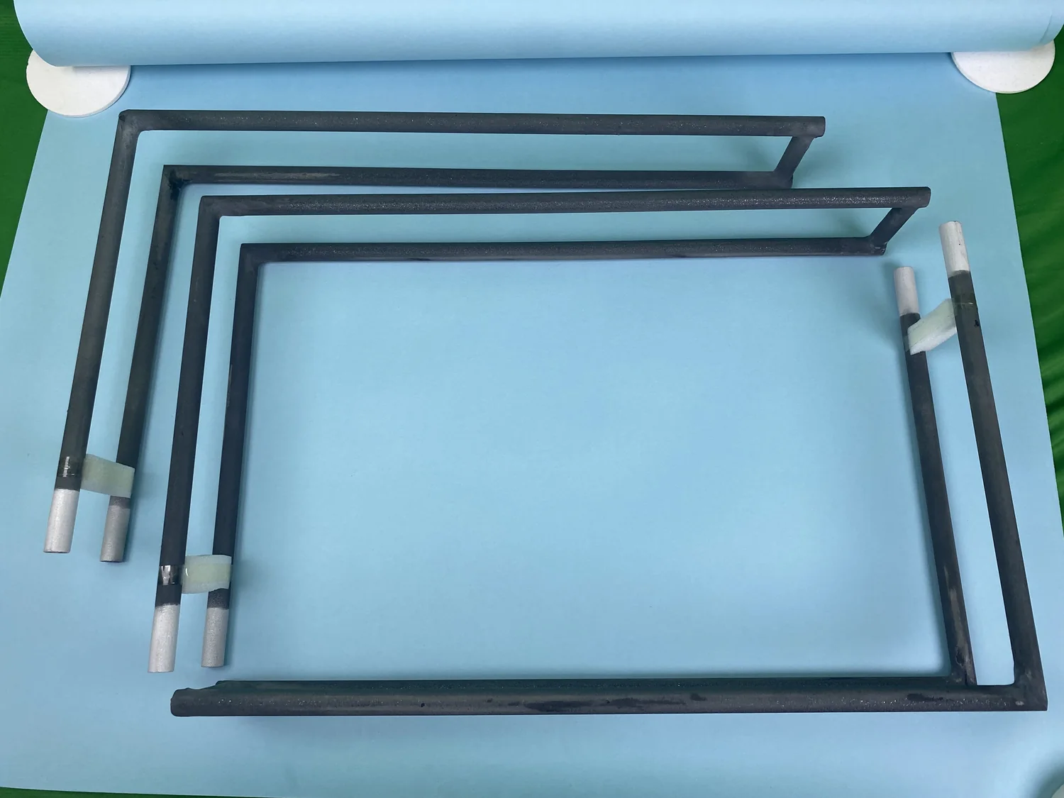
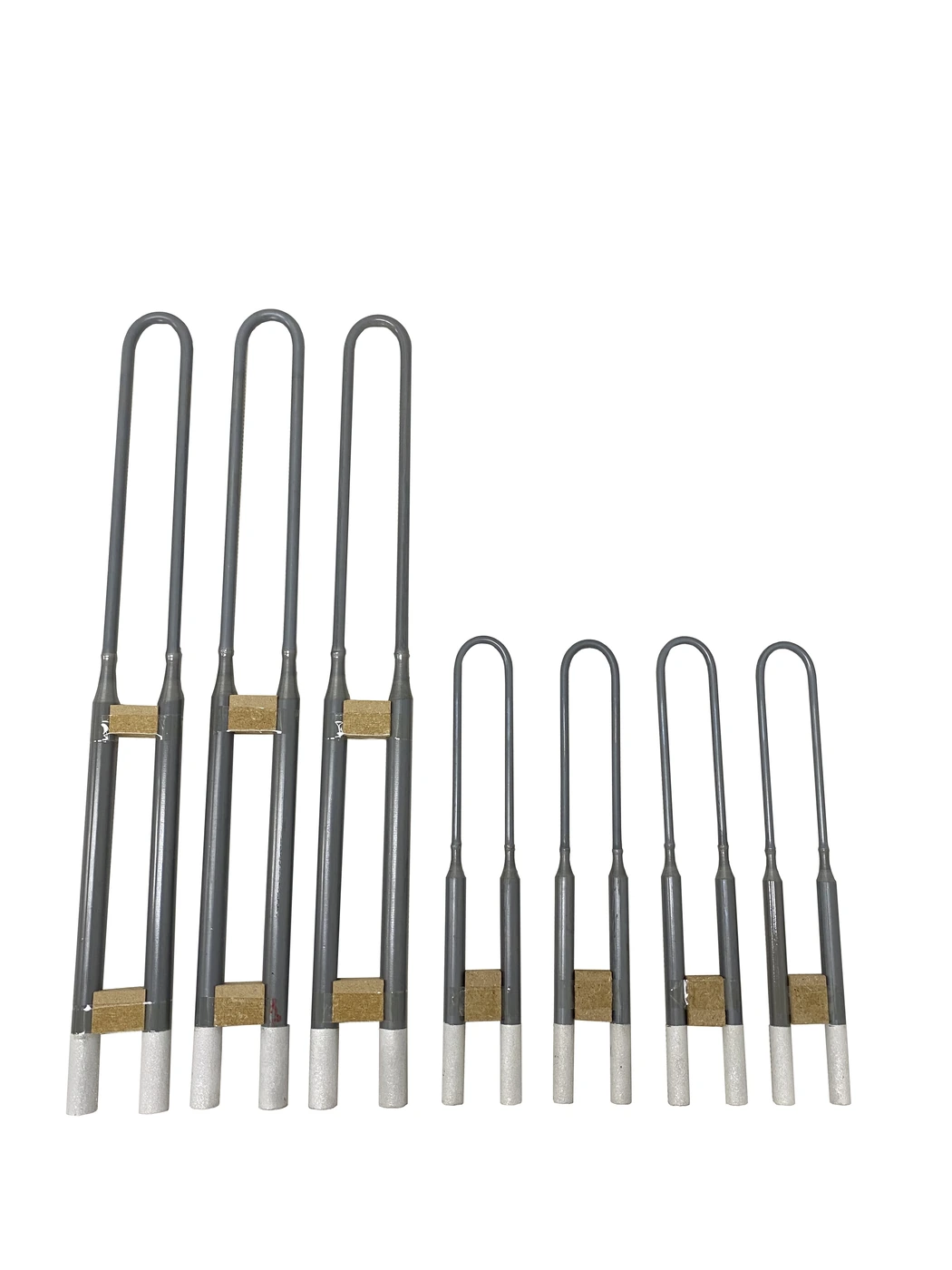
Silicon Carbide (SiC) Heating Elements and Molybdenum Disilicide (MoSi₂) Heating Elements use different shapes, surface loading, electrical behaviour, installation details and atmosphere limits. The correct route follows from the furnace duty and verified product data; neither element type should be presented as a universal upgrade for every application.
4. Draw the element and heated space together
Provide the chamber or tube geometry and mark element positions, load envelope, sensor, door or lid, insulation thickness and required clearances. For each element, show overall shape, heated zone, cold ends, terminal section, bend or shank geometry, spacing and support points. Heating length must be distinguished from total element length.
5. Define the electrical circuit before ordering replacements
Record voltage, phase, transformer or controller arrangement, element quantity, series or parallel grouping, circuit resistance and available power. For a replacement, provide the original drawing, nameplate data, cold-resistance measurements where appropriate and photographs of wiring and terminals. Do not substitute one element from appearance alone.
6. Account for resistance change and grouping
Element electrical behaviour can change with manufacturing tolerance, temperature and service exposure. State whether the project is a complete new set, partial replacement or furnace redesign. The supplier and furnace engineer must review grouping, matching, control range and the consequences of mixing elements with different service histories.
7. Design terminals and connections for the real installation
Confirm terminal diameter or section, connection method, straps or braids, contact area, tightening access, insulation and enclosure clearance. Keep electrical connections outside incompatible hot or contaminated regions. Expansion, vibration and maintenance access must not transfer harmful load to brittle element sections.
8. Protect the element mechanically
Show support points, hanging or standing orientation, penetration through insulation, clearances from the load and the path used for installation and removal. Element geometry must accommodate thermal expansion without contact with walls, fixtures, process tubes or adjacent elements.
9. Coordinate sensing and power control
The thermocouple, controller, power-control device, transformer and over-temperature protection must suit the element and furnace response. Identify the controlled zone, sensor type and position, required ramp control, alarms and data. A faster controller response does not compensate for an incorrectly sized element or unsuitable atmosphere.
10. Prepare a replacement evidence package
- Photographs of the complete furnace and installed element arrangement
- Element drawing with all heated, cold-end and terminal dimensions
- Material or confirmed element type, quantity and grouping
- Supply, transformer, controller, power and circuit information
- Original and measured resistance data where available
- Working temperature, full cycle and atmosphere
- Failure location, service history and observed deposits or damage
- Terminal, connector, support and installation-clearance details
Heating-element RFQ checklist
For a new furnace, send the chamber drawing, working cycle, atmosphere, load and electrical supply. For replacement elements, add original dimensions, wiring, quantity, resistance, terminal photographs and service history. Final element material, size, power and connection are confirmed only after the complete furnace and circuit are reviewed.