
Select SiC elements as part of the furnace circuit
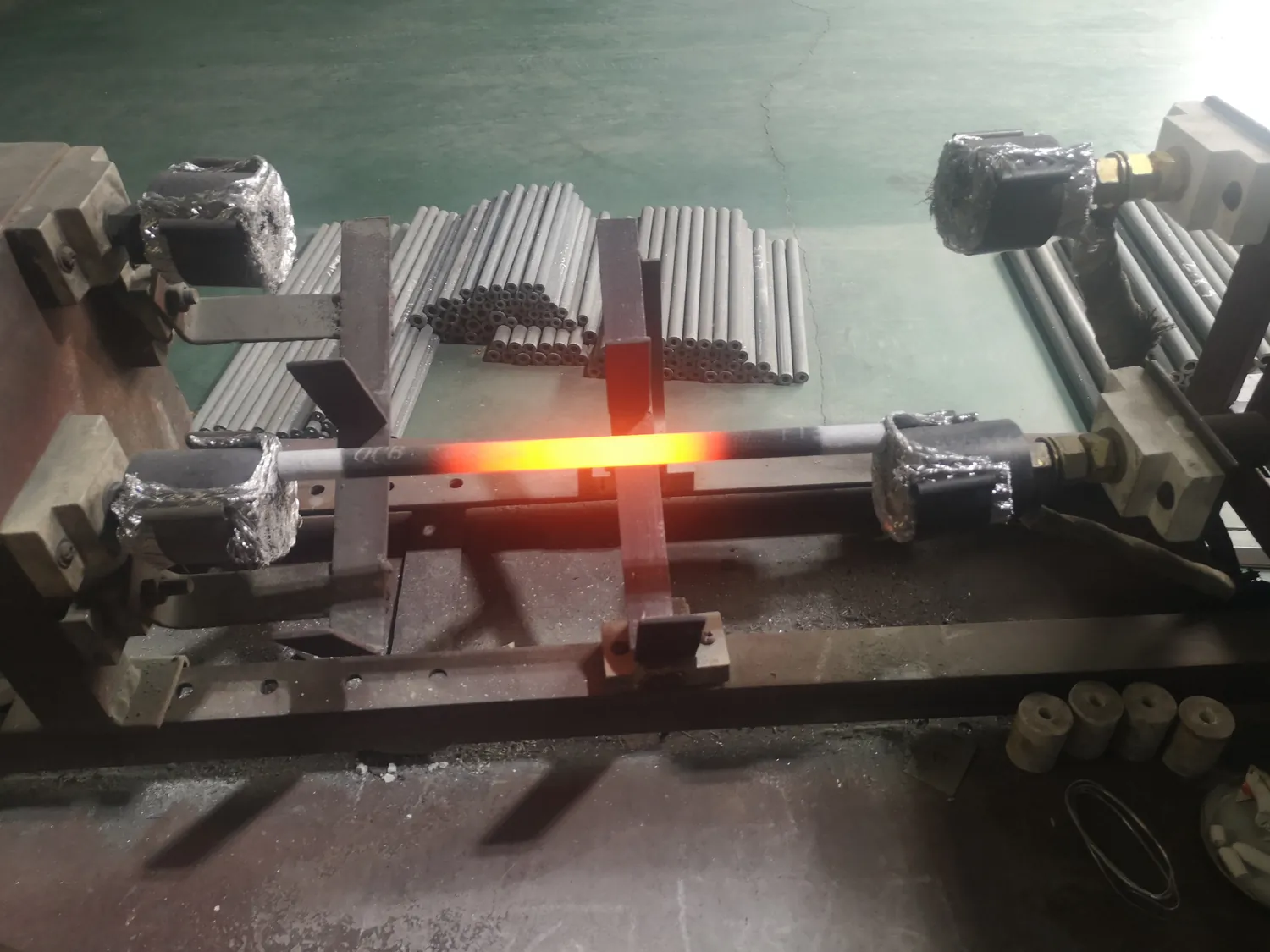
A silicon carbide heating element cannot be selected reliably from furnace temperature or a photograph alone. The element shape, heated section, cold ends, resistance, connections, support conditions and furnace atmosphere all belong to the same specification. Pyrocore uses the existing furnace data or the new furnace design as the starting point.
Define every active and inactive length
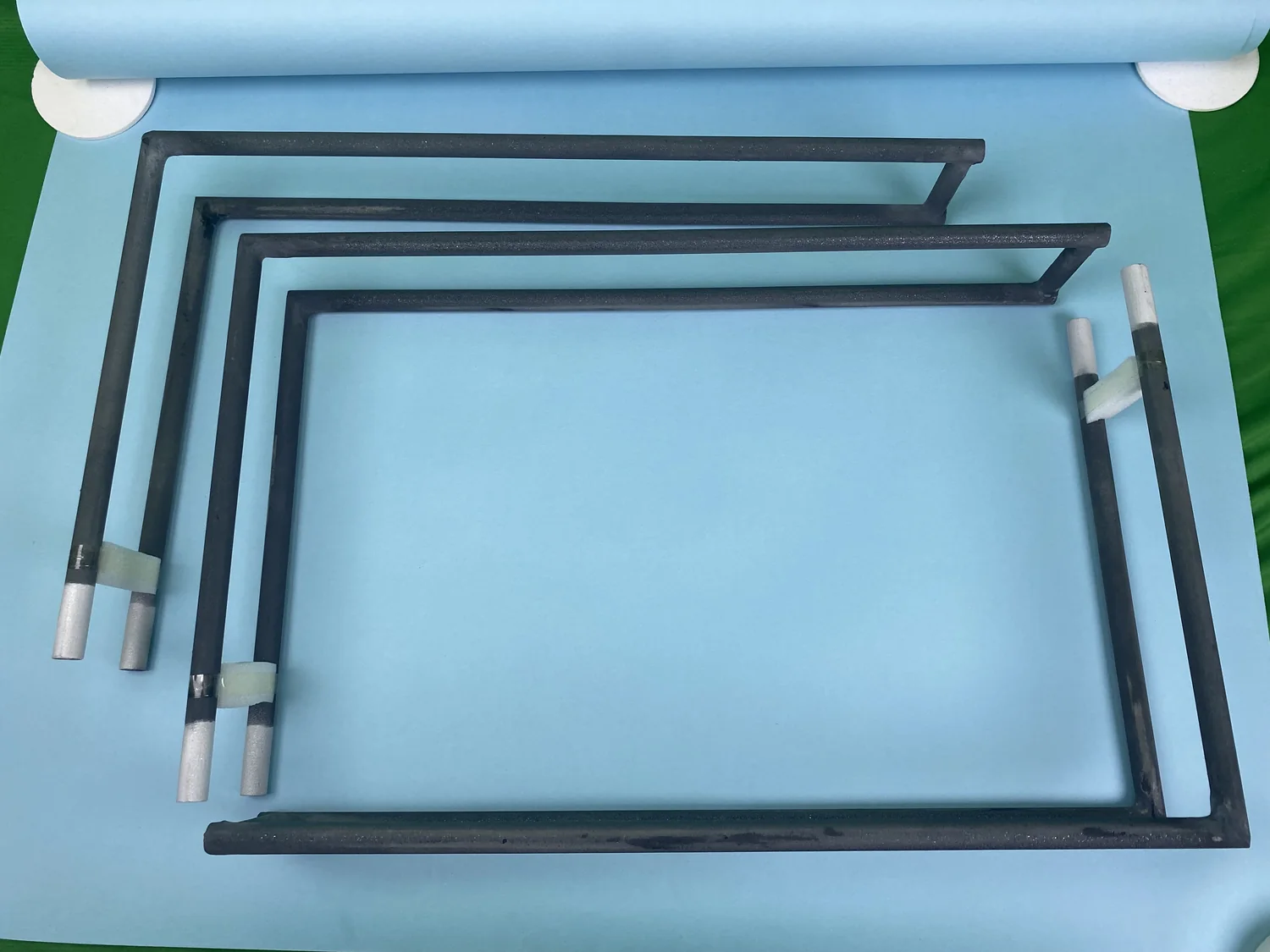
State the overall element length, heated or hot-zone length, cold-end length and diameter. For bent elements, include centreline dimensions, leg spacing and bend orientation. Mark which portion sits inside the insulation, which portion faces the load and where the electrical connection is made.
Match resistance and grouping
Replacement inquiries should include the measured or documented element resistance and the number of elements in each controlled group. Also provide the furnace supply, transformer information where used, connection arrangement and controller output. Elements that fit physically can still be electrically incompatible.
Check the furnace atmosphere and cycle
Describe whether the furnace operates in air or another process environment, what materials are heated, whether binders or vapours are released and how often the furnace cycles. These conditions help define whether the proposed SiC element and surrounding installation are appropriate. No service-life promise should be inferred without the actual operating conditions.
Plan installation and replacement access
Element openings must allow the required clearance without creating unsupported spans or terminal interference. Show supports, insulation penetrations, terminal guards and the route for connectors. If replacing a broken set, photograph an intact element, the installed bank, the terminal area and the furnace nameplate or electrical drawing.
Send this SiC element specification
- Element shape and dimensioned drawing
- Hot-zone, cold-end and overall dimensions
- Required resistance or existing resistance data
- Quantity and electrical grouping
- Furnace working temperature and cycle
- Atmosphere, load and contamination information
- Terminal, connector and installation photographs
- Power supply and destination country
For a complete replacement-chamber project, include the information described on Box & Muffle Furnace Chambers.