
A distinct silicon carbide heated chamber route
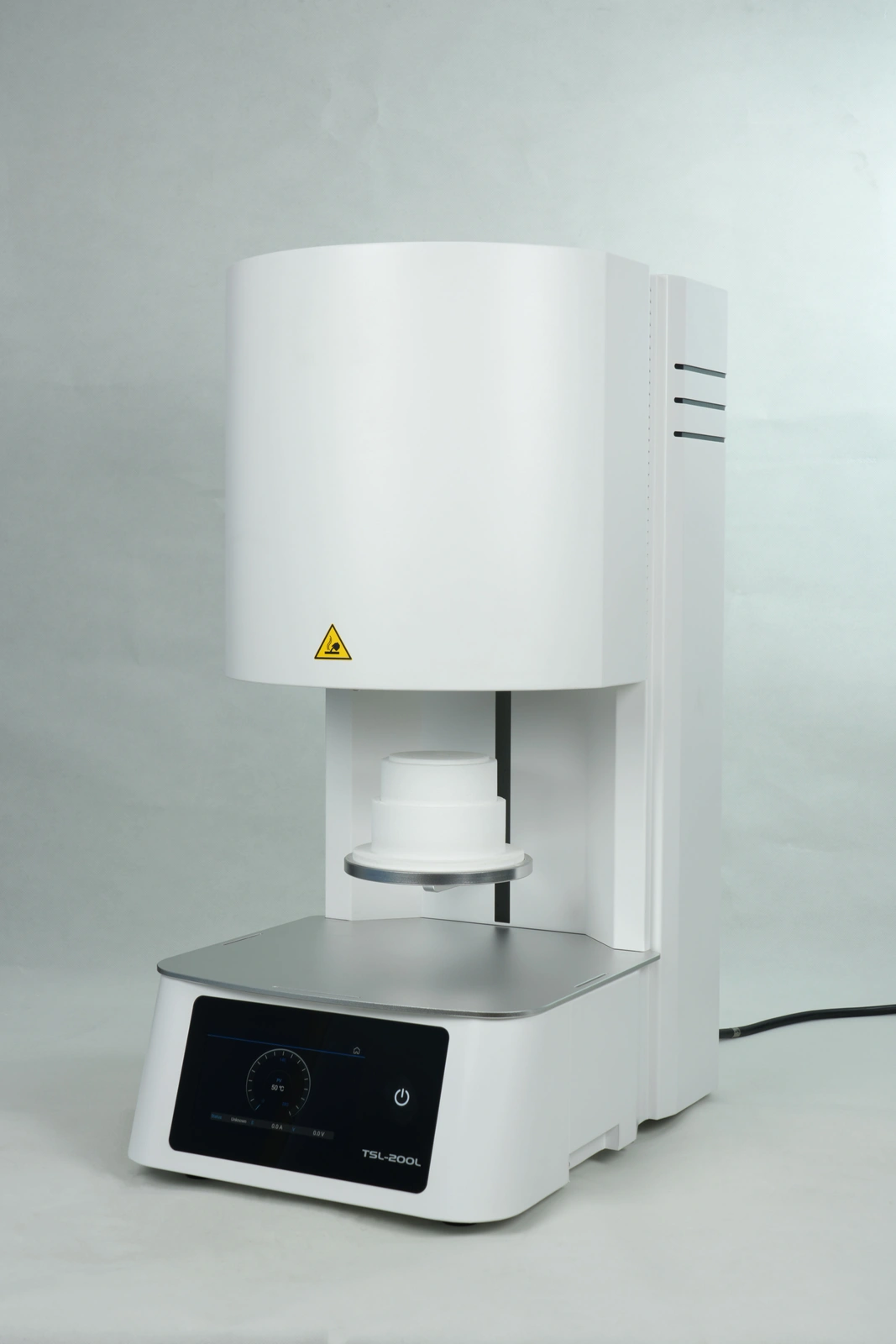
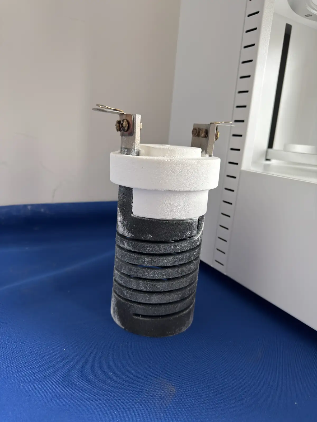
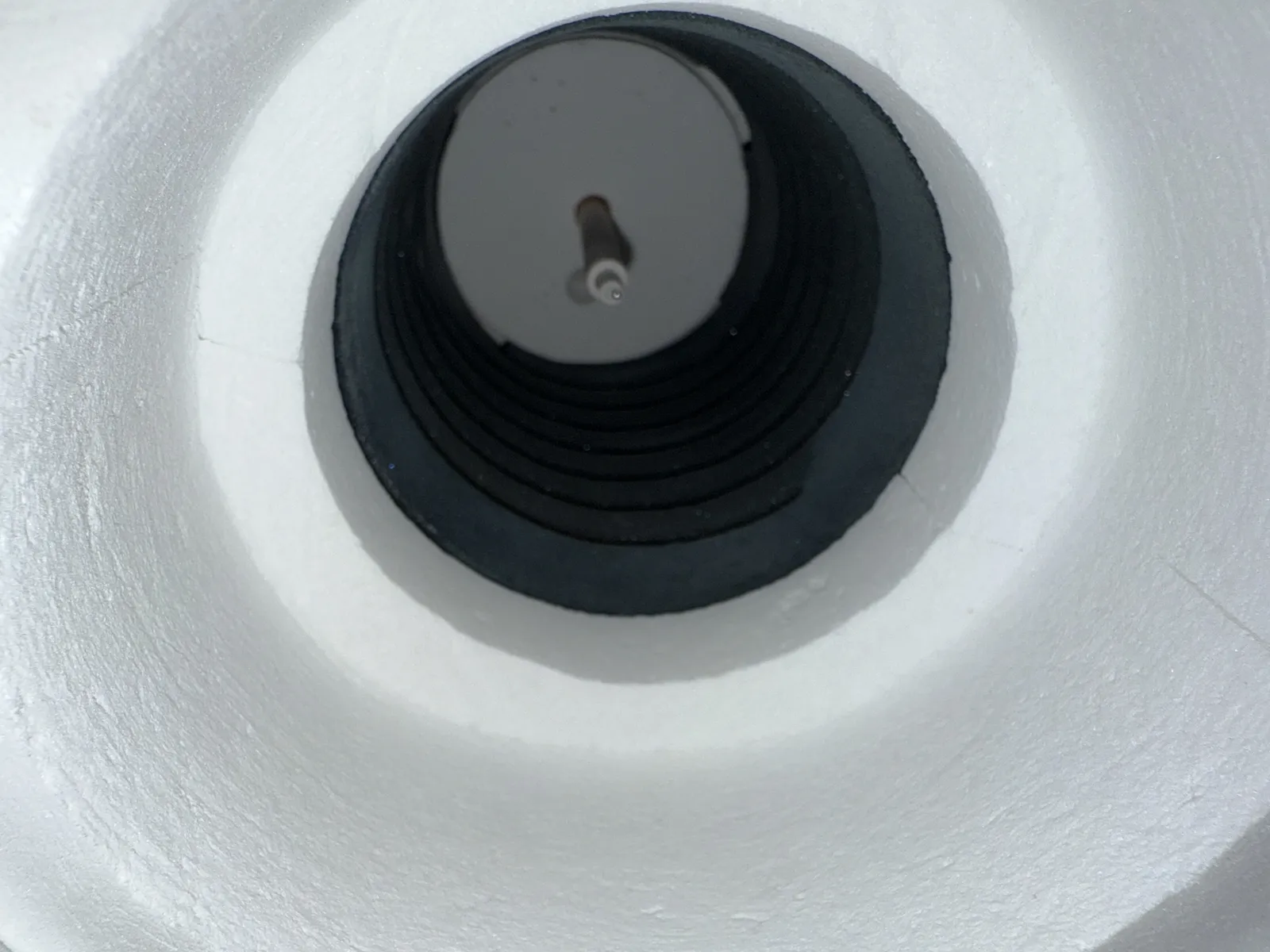
This furnace route uses a compact silicon carbide spiral heating assembly integrated with the insulated dental chamber. The element path, chamber bore, terminal arrangement, temperature measurement and lift platform must be selected as one system. It is a different configuration decision from the U-shaped MoSi2 chamber route.
Qualify the complete chamber module
The removable assembly evidence shows why chamber selection cannot be reduced to an element name. Terminal position, cold-end connection, insulated body, mounting, sensor route and the surrounding furnace enclosure all affect integration and service. Replacement and spare requirements should reference the selected assembly and electrical data rather than visual similarity alone.
Match the furnace to the zirconia instructions
Provide the material family, restoration types and complete approved program. Standard and accelerated programs should be identified separately. Pyrocore confirms the controller stages, heated chamber and cooling route against the requested workflow without treating a catalogue maximum as the operating condition.
Capacity depends on the real support system
Usable capacity is determined by the tray or crucible, support media, restoration spacing, vertical clearance and approved batch arrangement. Supply a photograph or drawing of the preferred load system when available. The normal batch and exceptional maximum should be evaluated separately.
Electrical and terminal integration
Silicon carbide element resistance changes during service, so the selected control and electrical arrangement must be compatible with the chamber design and intended duty. Final voltage, power, current, terminal and adjustment details are configuration-specific. For spare or replacement work, provide the furnace data, chamber photographs, terminal measurements and available electrical records.
Programs, cooling and laboratory operation
Discuss stored programs, editable stages, alarm handling, access control, calibration and any recovery expectations. The cooling sequence and chamber movement must follow the validated material route and the selected furnace instructions. Laboratory power, bench clearance and ventilation are part of the installation review.
Information required for a SiC dental furnace proposal
- Zirconia material system and current supplier instructions
- Complete ramp, hold and cooling programs
- Restoration types, batch arrangement, tray or crucible and support media
- Desired usable chamber clearance and lift-platform workflow
- Normal cycle frequency and service or spare-chamber expectations
- Voltage, phase, frequency, destination and control language
- Documentation, accessories, acceptance and validation requirements
Compare the fast MoSi2 dental sintering route, use the Dental Zirconia Furnace Specification Guide, or review Dental Furnace Chambers for chamber-level replacement and OEM requirements.