
Specify the heated chamber as a complete furnace interface
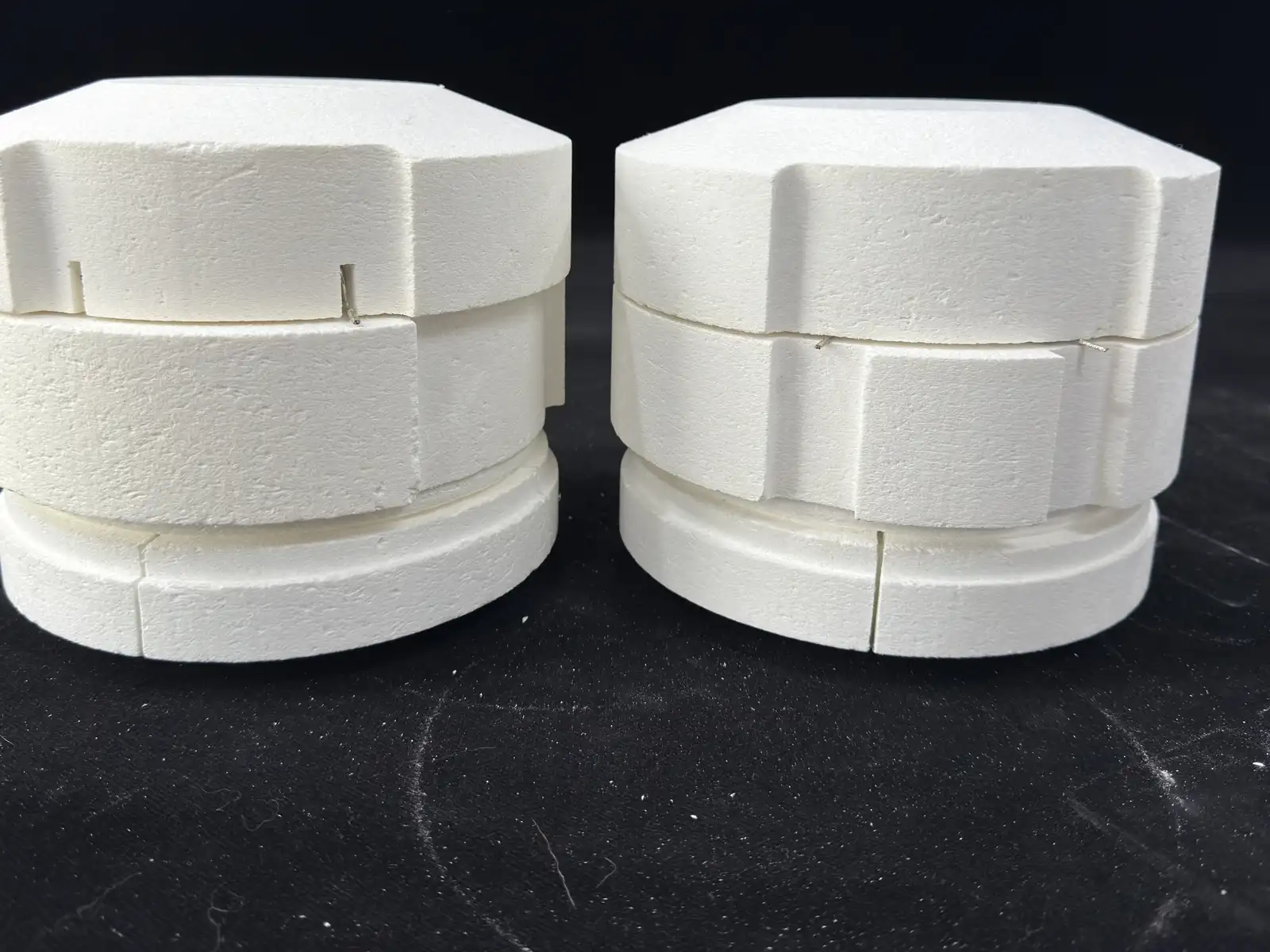
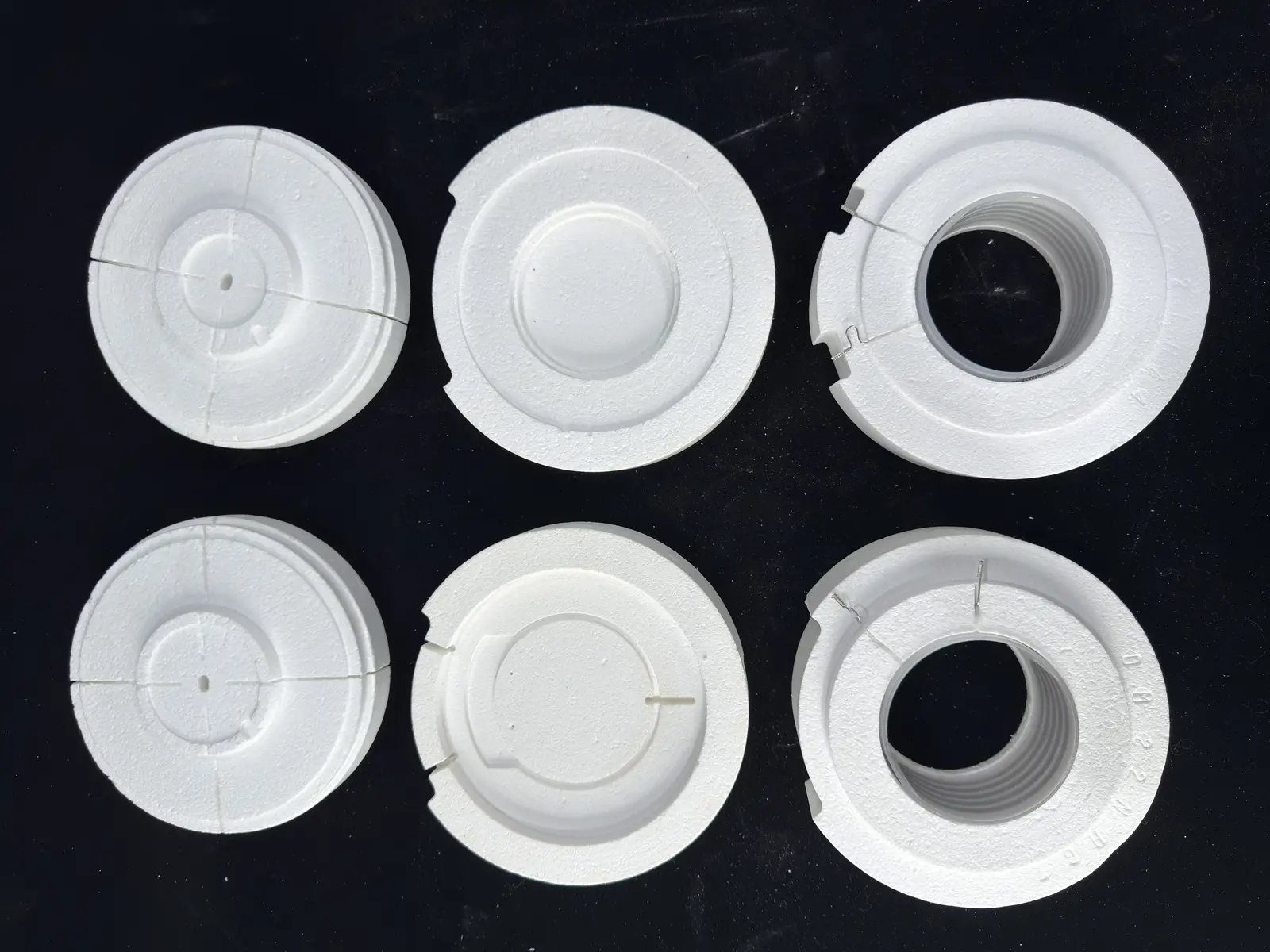
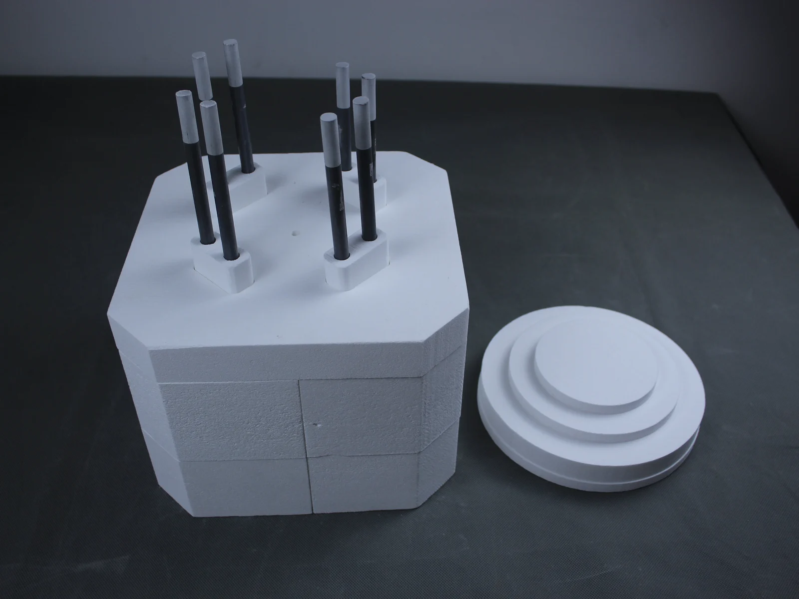
A dental furnace chamber is more than a shaped insulation part. It combines the usable hot space, element route, lid or platform interface, terminals, sensor access and external geometry required by a compact laboratory furnace. Pyrocore reviews both replacement chambers and new OEM integrations from the real furnace boundary rather than assuming interchangeability from an equipment name alone.
Distinguish replacement work from new furnace development
For replacement work, the objective is to reproduce or deliberately revise the interfaces needed by the installed furnace. For a new OEM furnace, chamber geometry can be developed with the enclosure, lifting platform or lid, controls and service access. State which route applies because the evidence, drawing responsibility and validation plan are different.
Measure the hot space and external body separately
Provide the internal diameter or working profile, usable depth, opening and load-support geometry. Then record the outside diameter, faceted profile, overall height, locating steps, mounting surfaces and enclosure clearances. Include separate dimensions for the lid, base, platform contact and every vent, thermocouple or lead opening. A furnace model reference can help identify context, but it does not replace a dimensioned drawing.
Coordinate the lid, base and loading movement
Compact dental furnaces may bring a platform into the chamber, lower a chamber over the load or use another qualified loading arrangement. Define which part moves, its travel, alignment, closure contact and hot clearance. The chamber opening, lid or base insulation, load tray and sensor must remain compatible throughout the complete movement.
Match the heating path to the working chamber
Element grooves or embedded heating paths are arranged around the required heated depth and chamber form. Provide the normal working cycle, load location, required control response and any known element information. Element material, wire size, path length, grouping and insulation are confirmed only after the thermal and electrical boundary is reviewed.
Record terminals, leads and sensor access
Send clear photographs of every terminal, lead-out and connector area. Record the available supply, phase, rated power, measured cold resistance, number of groups and controller arrangement where known. Provide the thermocouple type and insertion position if available. Terminal direction and lead clearance must fit the enclosure without creating contact with moving or hot components.
Use process evidence to qualify compatibility
Identify the dental material, holder or tray, batch geometry, programmed cycle and how an acceptable result is currently verified. A chamber that physically fits may still require a different element route, sensor position or control tuning. Final suitability is therefore confirmed against the complete furnace and process information.
Prepare a dental furnace chamber replacement package
Photograph the installed chamber before removal, then photograph the complete removed assembly, opening, underside, lid or base, terminals, sensor route and damaged areas. Add a dimensioned sketch and the available nameplate, wiring or controller data. Do not discard broken pieces until the replacement geometry has been reviewed.
Information required for a dental chamber RFQ
- Replacement or new OEM integration route
- Furnace arrangement and available reference photographs
- Internal hot-space dimensions and external chamber dimensions
- Lid, base, platform, opening, port and mounting geometry
- Dental material, load support and complete working cycle
- Supply voltage, phase, power, resistance and heating groups
- Terminal, lead, thermocouple and controller information
- Required supply boundary, quantity and destination country
For complete compact equipment, review Dental Laboratory Furnaces and Dental Zirconia Sintering Furnaces. For a general replacement workflow, use the Furnace Retrofit & Replacement Chambers application route.