
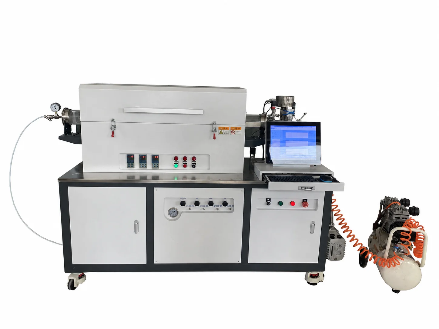
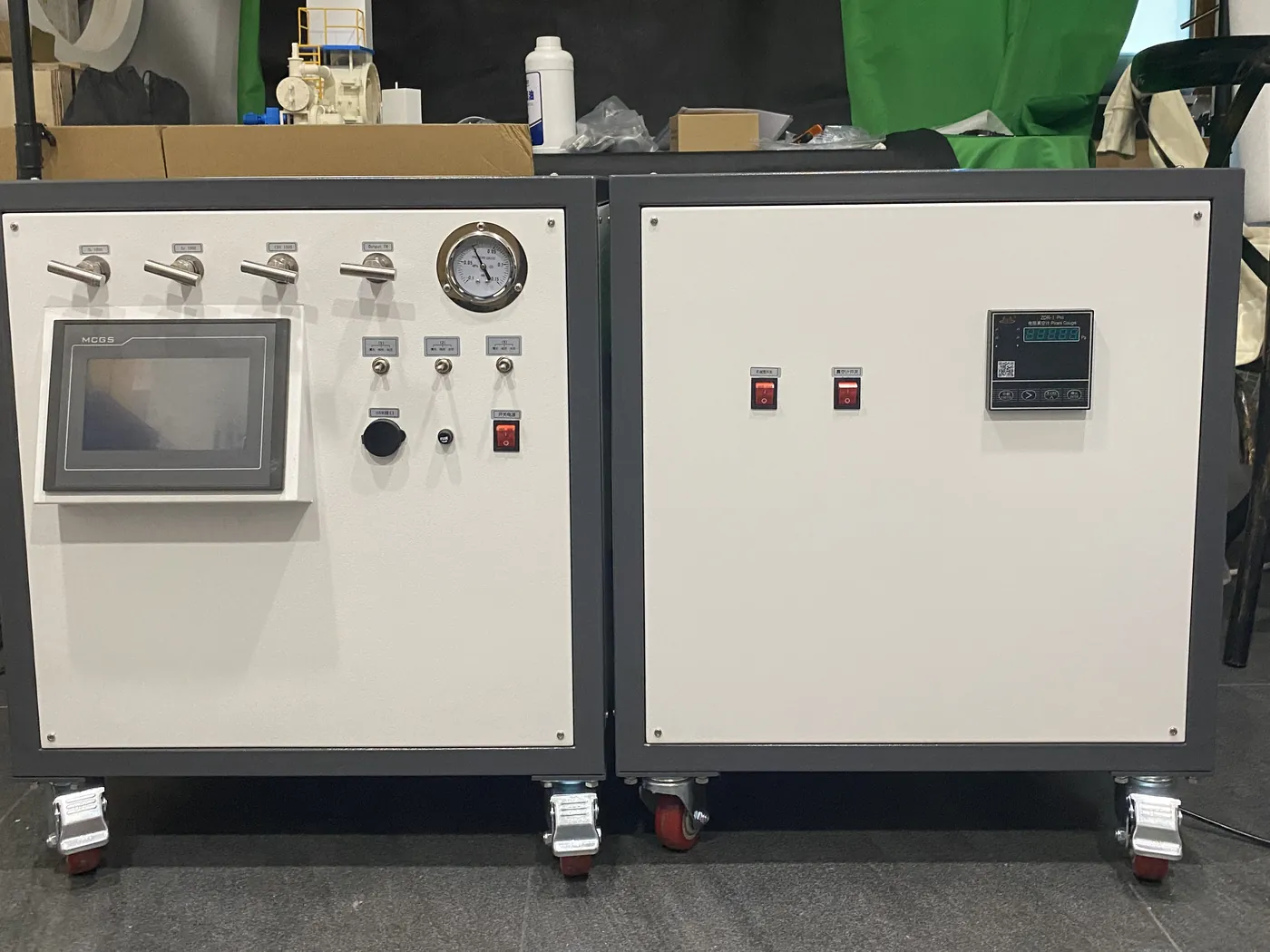
CVD equipment is a coordinated process system
A CVD tube furnace combines a heated reaction zone with gas delivery, process-tube seals, pressure measurement or pumping, exhaust handling and controls. A useful specification starts with the chemistry and substrate rather than selecting a furnace body and adding gas components later.
Define gas delivery before hardware selection
List every process and purge gas, the expected flow-control method and the sequence in which gases enter and leave the tube. Precursor delivery may require additional temperature control, containment or cleaning provisions. Materials compatibility and safety must be reviewed before the gas train is confirmed.
Place the substrate inside a defined thermal zone
Tube diameter alone does not define usable deposition space. State substrate geometry, holder, loading method and required position relative to each heated zone. If gradients or multiple regions matter, describe the intended profile so furnace length, zones and sensor locations can be reviewed together.
Controls and supply boundary
The requested automation can range from coordinated temperature and flow control to a sequence including purge, pressure, alarms and data recording. The proposal must identify which pumps, gas cabinets, precursor hardware, exhaust components and computer control are inside the supply boundary.
Send these project inputs
- Target material or film-development objective
- Substrate size, holder and process position
- Tube material, diameter and usable length
- Working temperature and zone/profile requirement
- Every precursor, carrier and purge gas
- Pressure, pump and exhaust-treatment boundary
- Automation, data, power and destination requirements
When plasma assistance is required, compare PECVD Tube Furnace Systems.