
Translate the process objective into a sample-temperature cycle
Rapid thermal processing and annealing applications are qualified from what must happen to the sample: its initial condition, required thermal exposure, atmosphere, acceptable cooling path and evidence of repeatability. The correct furnace route follows from those process inputs rather than from a nominal controller ramp alone.
Describe the material stack and desired change
Identify every material exposed to the cycle, including substrate, coating, fixture, boat, tube contact and any temporary layer. State the intended result in process terms such as annealing, stress relief, phase development or another qualified objective. Include known sensitivity to oxidation, volatilization, contamination or thermal shock.
Write the cycle as physical stages
- Load the sample and establish the starting environment.
- Purge, flow or prepare the required process atmosphere.
- Move the sample or heating enclosure into the defined hot position.
- Control exposure using the agreed time and sample-temperature evidence.
- Withdraw to the defined cooling position and continue the required atmosphere.
- Confirm the safe unload condition and retain the required cycle record.
This stage map exposes the movement, seal, gas and control interfaces that a single temperature value cannot describe.
Distinguish controller response from sample response
Tube material, sample mass, holder design, gas flow and sensor distance all influence the sample. State whether the development goal is comparative screening or a measured process window. When a defined sample ramp or peak is important, specify the thermocouple attachment or another measurement method, its location and the acceptance tolerance.
Control atmosphere through heating and cooling
Some samples remain sensitive after leaving the hot position. Define when gas flow begins, whether it continues during cooling, how oxygen or moisture exposure is limited and when the system may be opened. Gas safety, exhaust treatment and pressure relief remain part of the complete process review.
Qualify holders, fixtures and tube compatibility
The holder must support the sample throughout acceleration, exposure and withdrawal without creating an unintended contamination or heat-transfer path. Provide holder material, contact area, orientation and mass. Confirm that the process tube, seals and fixture materials are compatible with the intended temperature, gas and pressure conditions.
Choose the furnace route from the cycle
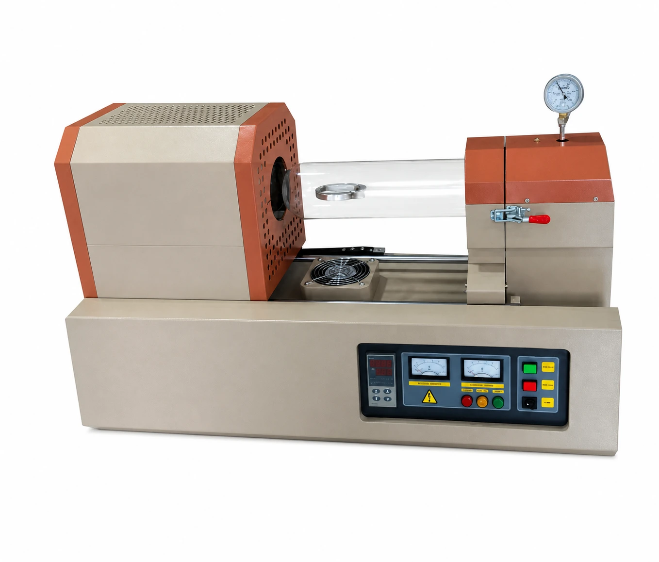
A sliding RTP tube furnace is a strong candidate when deliberate transfer between hot and cooling positions is central to the cycle. A multi-zone tube furnace may fit when the load remains in a stationary tube but experiences independently controlled axial sections. A standard tube furnace may be sufficient when rapid transfer is not the governing requirement.
Move from development to repeatable operation
Record sample position, holder, tube, atmosphere sequence, controller recipe, movement timing and measured sample evidence during development. Before repeat production, define allowable variation, calibration expectations, preventive checks and the response to incomplete movement, gas loss or over-temperature alarms.
Process information to send with an inquiry
- Material stack, sample geometry, quantity and holder
- Process objective and current baseline method
- Required sample ramp, exposure, dwell and cooling condition
- Gas species, purity, flow, pressure, purge and exhaust
- Tube and seal preferences or existing equipment interfaces
- Movement sequence and available installation envelope
- Measurement, data and repeatability requirements
- Known hazards, contamination limits and documentation needs