
Build the cycle around the sample, not a headline heating rate
A rapid thermal processing tube furnace uses controlled movement between a heating position and a cooling or loading position to create a defined thermal exposure. The useful engineering question is the temperature history of the sample under the actual tube, holder, atmosphere and movement sequence. A cabinet setpoint or unloaded furnace response does not by itself establish the process result.
Choose how the sample enters and leaves the hot zone
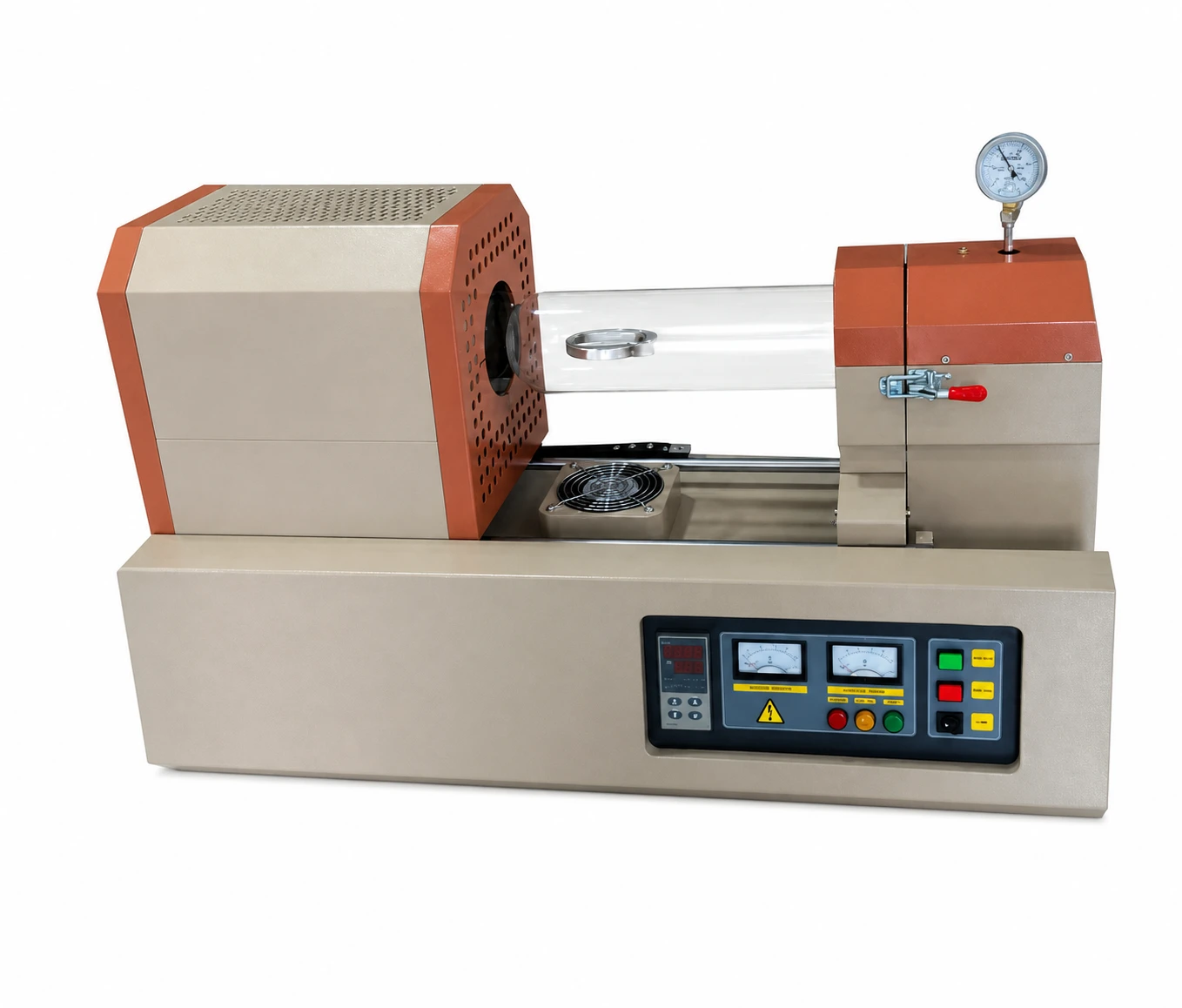
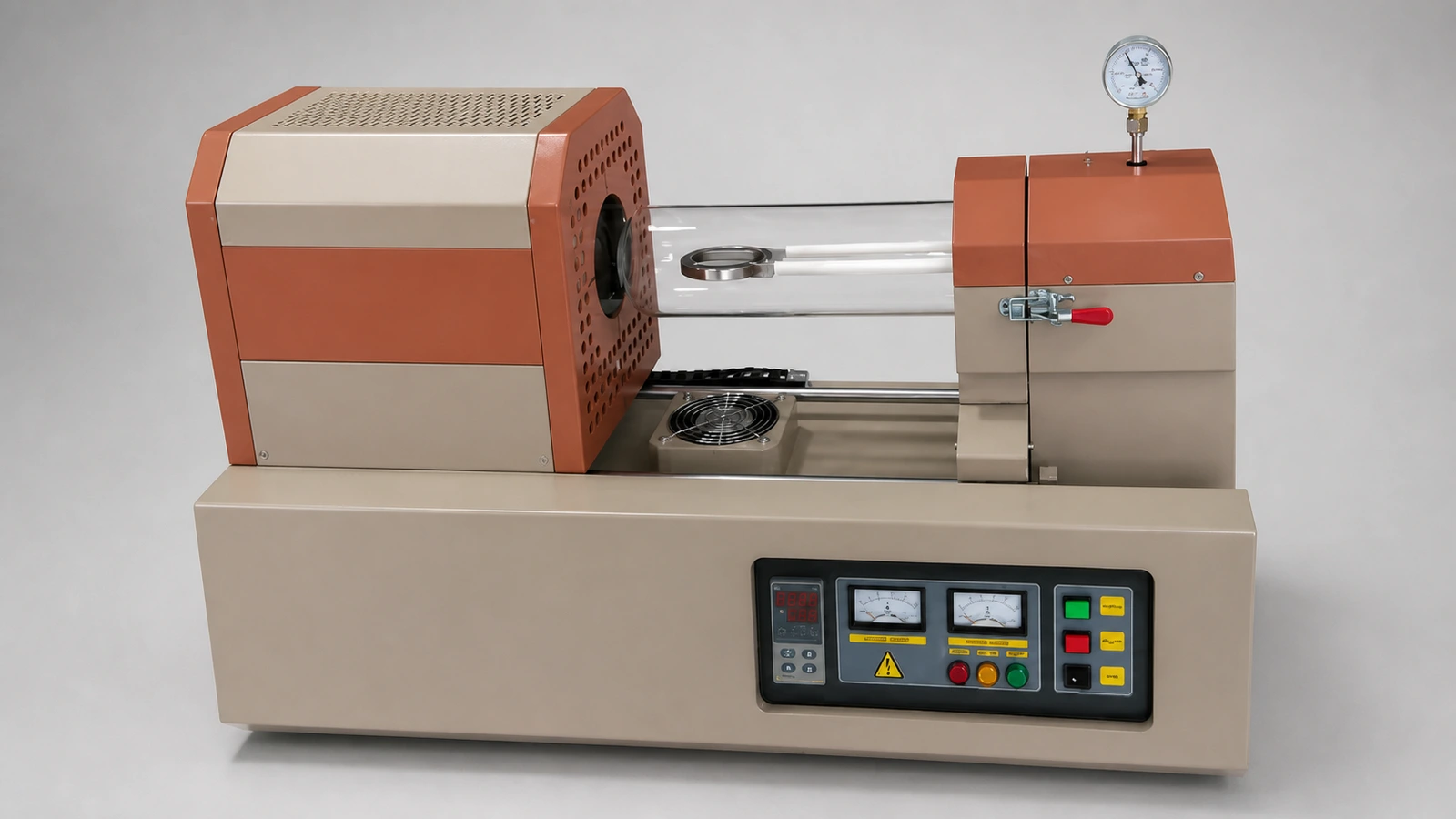
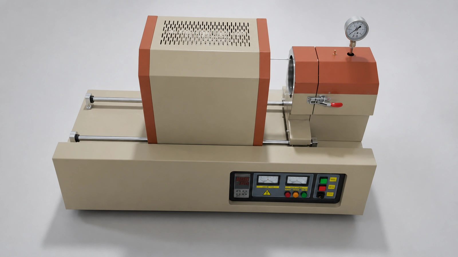
In a sliding-furnace arrangement, the process tube and sample position can remain fixed while the heated enclosure moves along a guided base. Another design may move the sample carrier relative to a stationary hot zone. State which motion is preferred, what remains connected during travel and how operators load, observe and service the system.
Define the tube, carrier and sample as one assembly
Provide the process-tube material, outside and inside diameters, total length and support method. Add the sample dimensions, holder or boat, thermocouple route, insertion depth and the required clearances. The thermal mass and position of every item in the tube can affect heating and cooling behaviour.
Separate furnace temperature from sample temperature
The control sensor regulates the heating enclosure from its installed position. The sample can respond differently because of tube transmission, load mass, gas flow, holder contact and movement timing. If the process requires a measured ramp, peak or cooling profile, define a load thermocouple or another agreed verification method and state where it must be measured.
Map the complete movement sequence
Describe the loading position, purge or atmosphere preparation, heating position, exposure time, withdrawal sequence and cooling position. Include travel limits, stopping accuracy, tube supports, flexible service connections, hot-surface protection and any interlock required before movement. The rail and surrounding workspace must remain clear throughout the cycle.
Qualify rapid cooling without assuming a result
Cooling depends on the sample, carrier, tube, surrounding air or qualified cooling arrangement and the distance from the heated enclosure. State the required sample-temperature endpoint and acceptable transfer method. Thermal shock, tube compatibility and safe access must be considered before a cycle is approved.
Define atmosphere and contamination controls
List the gas species, purity objective, flow direction, purge sequence, pressure objective, exhaust method and contamination limits. The process tube and end assemblies establish the sealed boundary. Vacuum capability, gas compatibility and allowable operating conditions are confirmed only for the complete configured assembly.
Plan for repeatability, records and safe motion
Specify the required cycle recipe, movement timing, alarms, over-temperature protection, position confirmation, gas or pressure interlocks and data records. For development work, identify which measurements are exploratory. For repeat production, define the acceptance evidence that must be reproduced from cycle to cycle.
Information required for an RTP furnace RFQ
- Material, sample geometry, mass and process objective
- Required sample-temperature history, exposure and cooling endpoint
- Process-tube material, diameters, length and support method
- Sample holder, carrier, loading and thermocouple arrangement
- Preferred furnace or sample movement sequence
- Hot position, cooling position, movement distance and available envelope
- Gas, purge, exhaust, pressure and contamination requirements
- Controls, interlocks, data recording and acceptance method
- Power supply, destination and documentation requirements
Review the process route on Rapid Thermal Processing & Annealing. For a stationary heated section, see Tube Furnaces. If independently controlled axial sections are required, compare Multi-Zone Tube Furnaces.