
Specify the furnace chamber as an integrated assembly
A furnace chamber is more than an insulation shape. Replacement, retrofit and OEM work can involve the usable hot space, external body, element path, terminals, thermocouple, door interface, vents, supports, metal shell and enclosure clearances. A dimensioned drawing and electrical evidence are therefore more reliable than a photograph or nominal furnace model alone.
1. Identify replacement, retrofit or OEM scope
State whether the chamber must reproduce an existing assembly, fit an altered furnace, or integrate into a new enclosure. Explain which surrounding parts will remain: door, frame, shell, controls, wiring, supports, process tube, lift platform or other mechanism. The supply boundary can range from a shaped chamber to a heated and instrumented assembly.
2. Measure internal and external geometry separately
Record usable width, height, depth or bore independently from outside dimensions and wall thickness. Add the chamber opening, rear wall, end sections, split line and any taper, radius or custom profile. For tube chambers, provide process-tube outside diameter, required clearance, heated length and total chamber length.
3. Map every opening and interface
Show door or lid opening, process-tube path, thermocouple hole, vent, sight port, element leads, terminal recesses, mounting holes, support ledges, grooves and service cut-outs. Dimension each feature from stable reference faces. Photograph the chamber from every side with a scale visible where practical.
4. Record the heating-element arrangement
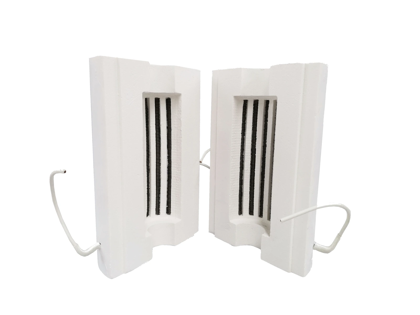
Identify element type, material where confirmed, groove or support route, heated faces, zones and lead-out direction. For resistance wire or integrated elements, provide wire diameter or section, coil information, route, terminal positions and photographs. For SiC or MoSi₂ arrangements, provide element shape, dimensions, quantity, grouping and clearances.
5. Provide electrical evidence
Record voltage, phase, frequency, rated power, zone count, controller arrangement and measured circuit or chamber resistance where available and appropriate. Include wiring photographs and terminal labels only after removing company or customer identity. Do not derive a replacement electrical design from chamber size alone.
6. Define the thermocouple and measurement position
Show thermocouple type if known, protection tube, insertion direction, depth and location relative to elements and load. State whether the existing sensor and controller will remain. A new chamber must preserve safe separation and provide a temperature signal representative of the intended control zone.
7. Describe door, lid or moving-platform interfaces
Provide the closed relationship between chamber opening and door insulation, including overlap, compression, gap and movement direction. For split, lift, bottom-loading, top-opening or pass-through arrangements, show hinges, guides, stops and clearance through the complete travel.
8. Include supports, shell and installation sequence
Show how the chamber is supported, retained and removed. Record shelves, base plates, frames, clamps, metal shell, external insulation and expansion clearance. Explain whether the assembly enters through the front, top, side or after the enclosure is disassembled.
9. State the process and environment
Provide working temperature, ramp, hold, cooling, load, atmosphere, pressure condition and known contaminants or vapours. A metal shell does not automatically create a gas-tight or vacuum boundary. Sealing, pressure and atmosphere performance depend on the complete furnace or vessel design.
10. Build a dimensioned evidence package
- Complete furnace and chamber overview photographs
- Photographs of all chamber faces, openings, damage and terminals
- Dimensioned inside and outside drawings from fixed reference faces
- Door, lid, split line, tube, sensor, vent and mounting interfaces
- Element route, terminal positions, zones and wiring photographs
- Voltage, phase, power, resistance, controller and thermocouple data
- Working cycle, atmosphere, load and service history
- Required supply boundary and surrounding parts that will remain
Choose the closest chamber route
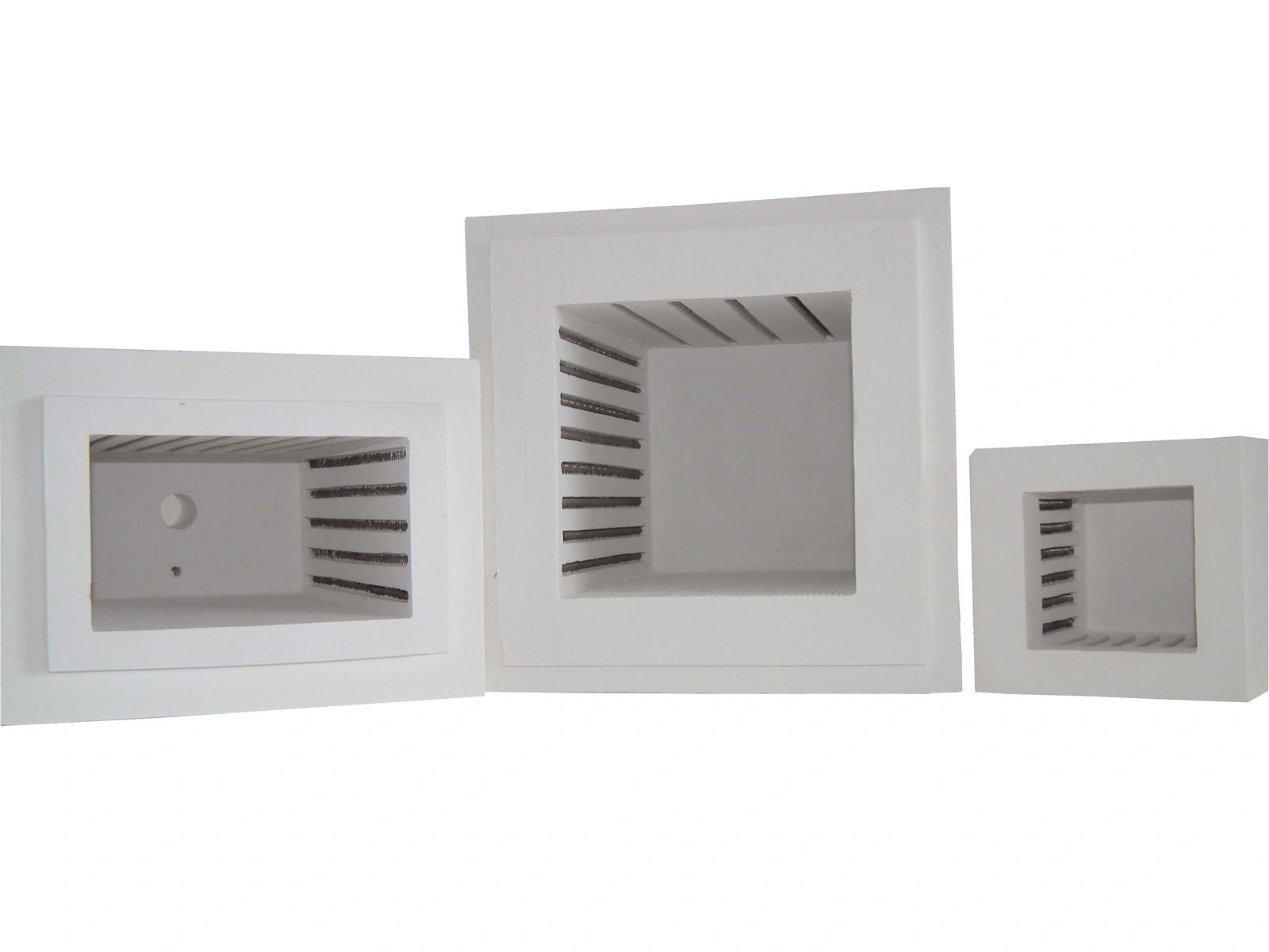
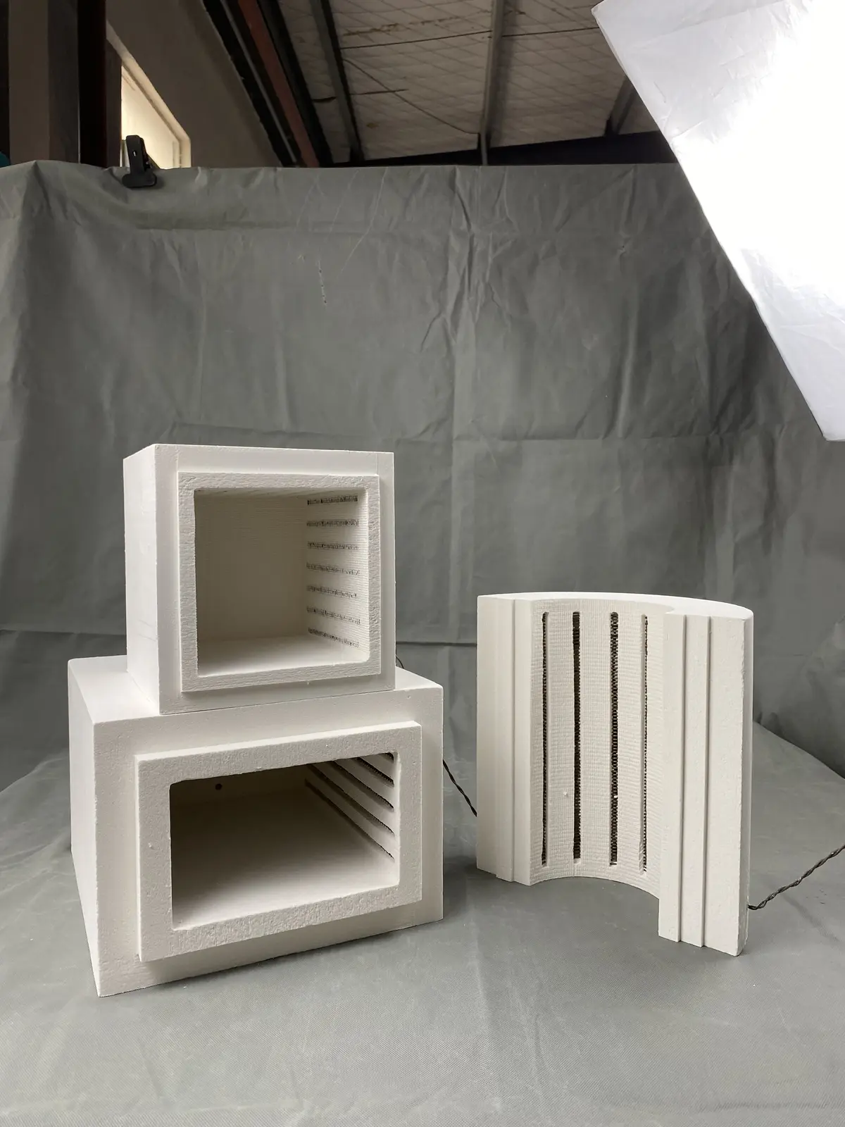
Use Box & Muffle Furnace Chambers for rectangular heated spaces, Tube Furnace Chambers for cylindrical or split tube-heating assemblies, and Custom-Shaped Furnace Chambers when the geometry does not fit a standard form. Dental, metal-shelled and diffusion-furnace chamber routes are available for their specific integration requirements.