
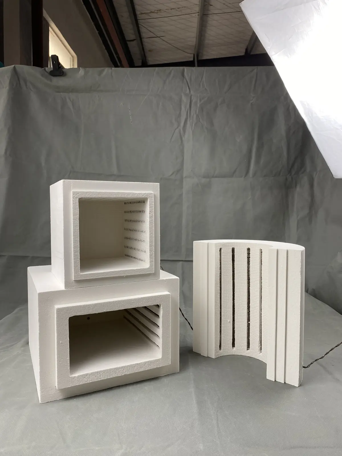
Connect the hot space with the complete furnace interface
Pyrocore has expanded its furnace chamber information for technical buyers planning replacement, retrofit or OEM integration. The chamber portfolio now covers box and muffle, tube, metal-shelled, custom-shaped, dental and diffusion furnace chamber routes, supported by a dedicated chamber specification guide.
The expanded material treats a furnace chamber as an engineered heated assembly. Generic ceramic fiber board, blanket, paper and other standalone refractory materials are not presented as this product route. A chamber inquiry instead connects the usable hot space with insulation geometry, heating paths, sensors, terminals, openings, mounting and the surrounding equipment.
Replacement projects begin with evidence
A photograph of a damaged lining is not enough to reproduce a compatible chamber. Replacement review should include overall furnace photographs, every chamber face, openings, terminal areas, sensors and supports, together with a dimensioned sketch. Existing nameplate and electrical information can help establish the original boundary, but final compatibility still depends on the submitted condition and requested duty.
Separate inside, outside and interface dimensions
Usable space and exterior size answer different questions. The inside dimensions define load clearance and the heated process region. The outside dimensions define enclosure fit. Wall thickness, door relationship, split line, tube bore, vents, sensor openings, element exits and support features must be measured separately. A replacement can fail even when one overall dimension appears correct.
Match the heating path to the furnace duty
Heating-element material and geometry are selected against working temperature, atmosphere, duty cycle, chamber construction and electrical circuit. Available voltage, phase, power, resistance, zone count, control method and terminal arrangement should be recorded. A change to insulation thickness or element route may affect power density, heat loss, response and the connected control system, so it must be reviewed as an engineering change rather than a cosmetic copy.
OEM integration requires an interface drawing
For new equipment, the chamber can be discussed as a shaped insulated body, a chamber with installed heating elements or a more complete metal-shelled assembly. The OEM drawing should identify every mounting surface, opening, cable or terminal path, sensor, door or split movement, service clearance and acceptable assembly tolerance. The final supply boundary should also identify which party provides the outer enclosure, controls, wiring and safety functions.
Prepare a technically useful chamber inquiry
- State replacement, retrofit or OEM integration duty
- Send furnace overview and chamber-detail photographs
- Provide inside, outside, opening and mounting dimensions
- Describe the load, working cycle and atmosphere
- Include available voltage, phase, power, resistance, zones and control information
- Mark elements, terminals, sensors, vents, doors, split lines and supports
- Identify quantity, utilities, destination and requested documentation
Browse Furnace Chambers, use How to Specify a Furnace Chamber, or review the Furnace Retrofit & Replacement Chambers application route.