
A larger tube changes the complete furnace system
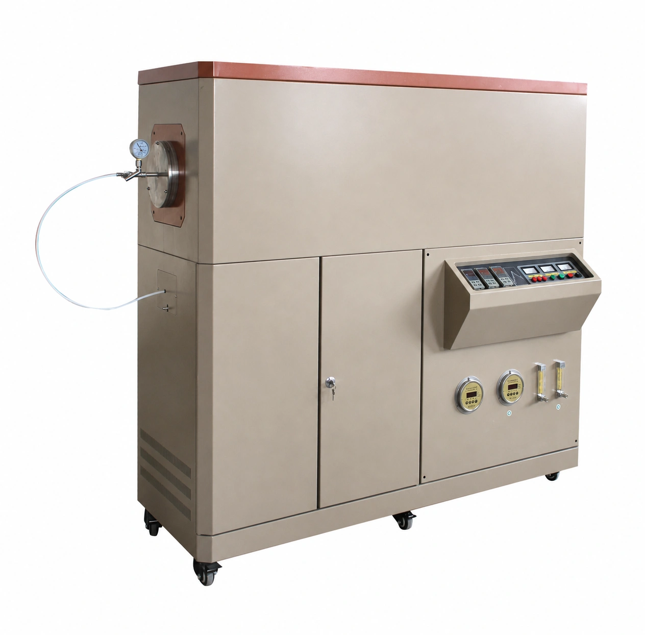
A large-diameter tube furnace is not simply a compact furnace with a wider opening. Tube mass, support, flange load, sample envelope, heated profile, gas volume, sealing and installation access all change with scale. The floor-standing equipment shown is a configuration example with a large tube interface, multi-section controls, pressure indication and flow-management instruments; final dimensions and performance are project-specific.
Start with tube integrity and mechanical support
Provide the proposed tube material, outside diameter, inside diameter, wall thickness, total length and expected operating conditions. Define the support points, end assemblies and allowable flange loads. Tube deflection, thermal expansion and handling must be reviewed with the installed orientation and load.
Define the real usable load envelope
State the sample or product dimensions, holder, batch mass, quantity, loading direction and required working clearance. The tube inside diameter is not the same as usable load diameter after allowing for the holder, sensor, gas path and safe insertion. Include any boat, tray, plug or internal fixture in the dimensional review.
Build the heated profile around the process
Specify the normal working temperature, ramp, hold, cooling and required axial profile. If several controlled sections are needed, describe the purpose of each section and the acceptable relationship between them. Control-sensor readings, tube response and loaded sample temperature should be separated in the acceptance plan.
Size the gas and pressure system for the larger volume
A larger tube may require a different purge volume, flow strategy, pumping boundary and exhaust arrangement. Provide gas species, purity, number of flow channels, required flow range, operating-pressure objective, measurement method and exhaust destination. All gas and pressure performance is confirmed only for the complete configured system.
Coordinate controls and protection
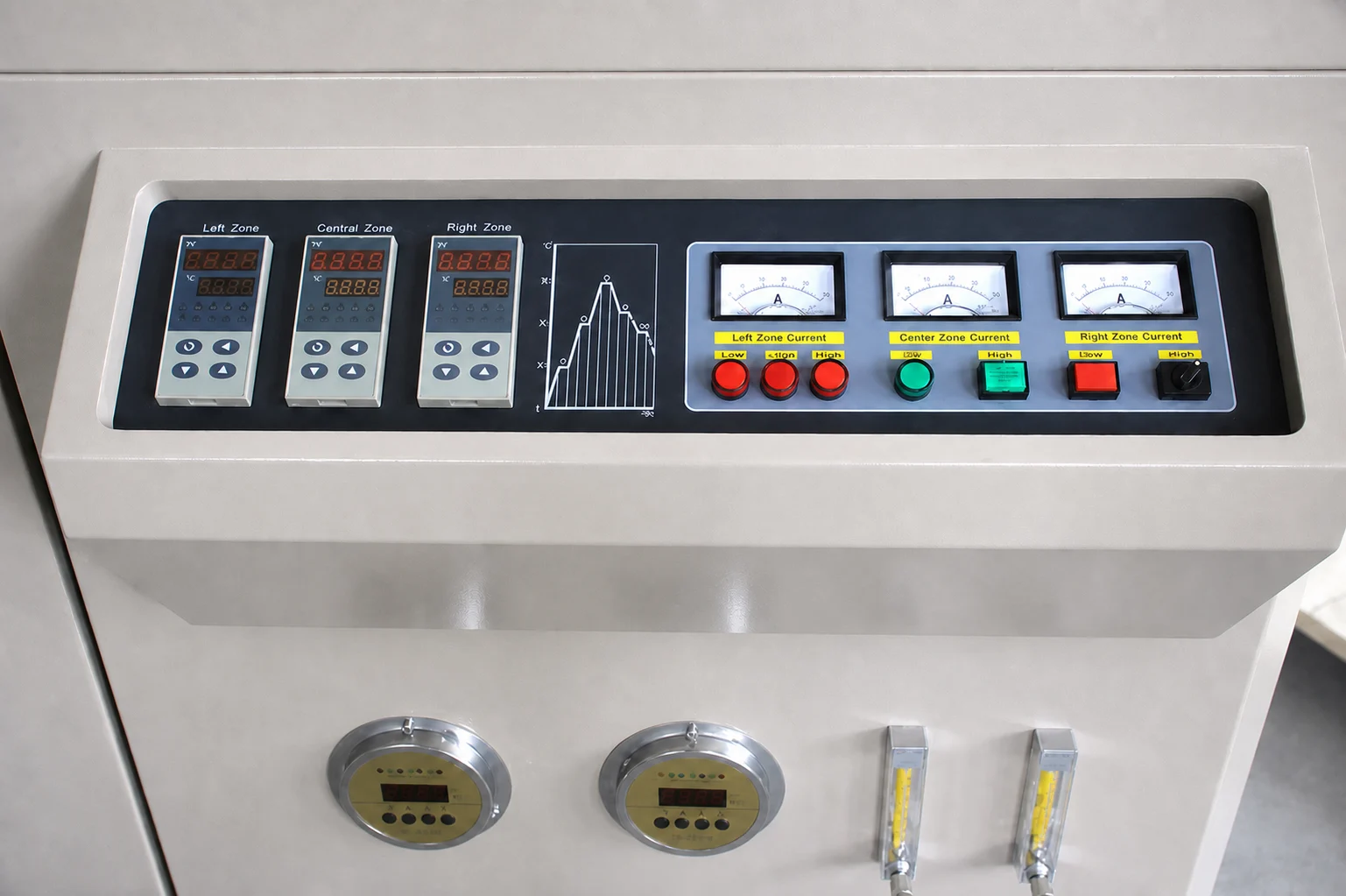
The illustrated control architecture includes multiple temperature-control sections, zone-current indication and separate flow-management instruments. The final system may use a different approved arrangement. Define recipe control, sensor count, data recording, alarms, over-temperature protection, gas or pressure interlocks and emergency response requirements.
Plan installation and service access early
Provide the destination power supply, available floor area, doorway and lifting constraints, ventilation, exhaust, gas supply and service clearances. Include the required access to cabinet doors, controller console, tube ends, flanges and instruments. State whether the equipment must be movable for installation or permanently located.
Information required for a large-diameter tube-furnace RFQ
- Material, process objective, sample geometry, holder and batch mass
- Tube material, outside and inside diameters, wall and total length
- Required usable hot length, controlled sections and sample position
- Normal working temperature and complete thermal cycle
- Gas species, purity, flow channels, pressure and exhaust
- Tube supports, end assemblies, ports, valves and flange requirements
- Control, data, alarm, interlock and acceptance requirements
- Power supply, utilities, footprint, access and destination
For a smaller fixed heated section, compare Compact Single-Zone Tube Furnaces. For independently controlled axial heating sections, review Multi-Zone Tube Furnaces.