
Project requirement
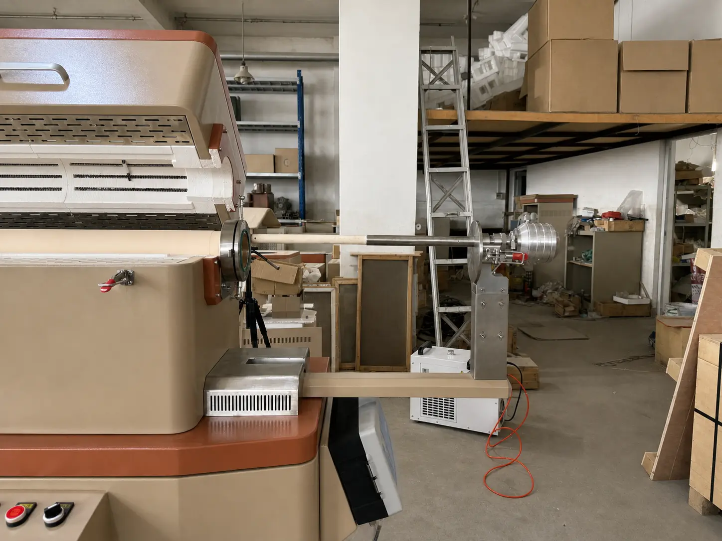
The equipment evidence shows an open split tube furnace aligned with a long ceramic process tube and an extended metal probe or sensor assembly. A guided base and independent support post keep the heated enclosure, flange and probe on a common axis. The key engineering task is not only heating: it is maintaining alignment and a defined relative position through loading, movement and operation.
Put every axial position on one drawing
The furnace centreline, heating-element region, insulation ends, process-tube ends, flange faces, probe tip, sample position and support points should share one dimensioned axial view. Describing only furnace width or probe length leaves the most important working relationship undefined.
Support the probe independently
The visible metal support carries the extended probe assembly rather than transferring its full mass to the ceramic tube or seal. A similar project should define probe weight, insertion, adjustment, thermal expansion and any cable or instrument load. Support stiffness and alignment influence the flange and process-tube interface.
Define what moves and when
A sliding furnace can change the relationship between the hot enclosure and a stationary tube, probe or sample. State the starting position, process position, travel, stops, motion method and the temperature condition permitted for movement. Guards, hot-surface protection and cable routing must follow the complete travel envelope.
Coordinate split-chamber access with the tube
The open enclosure documents direct access to the process-tube position and the internal heating path. Bore clearance, split line, hinge direction, tube support and insulation ends must fit the installed tube without using the furnace shell as an unintended structural clamp.
Treat the flange as part of the process boundary
The flange, green seal and red-handled valve are visible configuration evidence, but they do not establish a universal pressure or gas rating. Specify tube material, flange family, seal exposure, process gases, temperature at the seal, pressure sequence, pumping, measurement and exhaust.
Place sensing around the real sample position
The control sensor regulates from its installed location; an inserted probe may measure another point or process condition. Identify which measurement controls the furnace, which records the sample or gas condition and how their positions relate. Define the evidence required during acceptance rather than assuming controller display equals sample response.
Information for a similar probe-interface project
- Material, process objective and complete thermal cycle
- Dimensioned furnace, tube, probe, flange and sample positions
- Probe material, diameter, length, mass and instrument connection
- Furnace travel, motion sequence, stops and safety boundary
- Tube material, dimensions, supports and replacement method
- Gas, pressure, sealing, pumping and exhaust requirements
- Sensor roles, data, controls and acceptance measurements
- Utilities, installation space, destination and documentation
Compare Rapid Thermal Processing Tube Furnaces for guided furnace movement and How to Specify a Tube Furnace for the complete tube-system boundary.