
Shape the heated chamber around the equipment interface
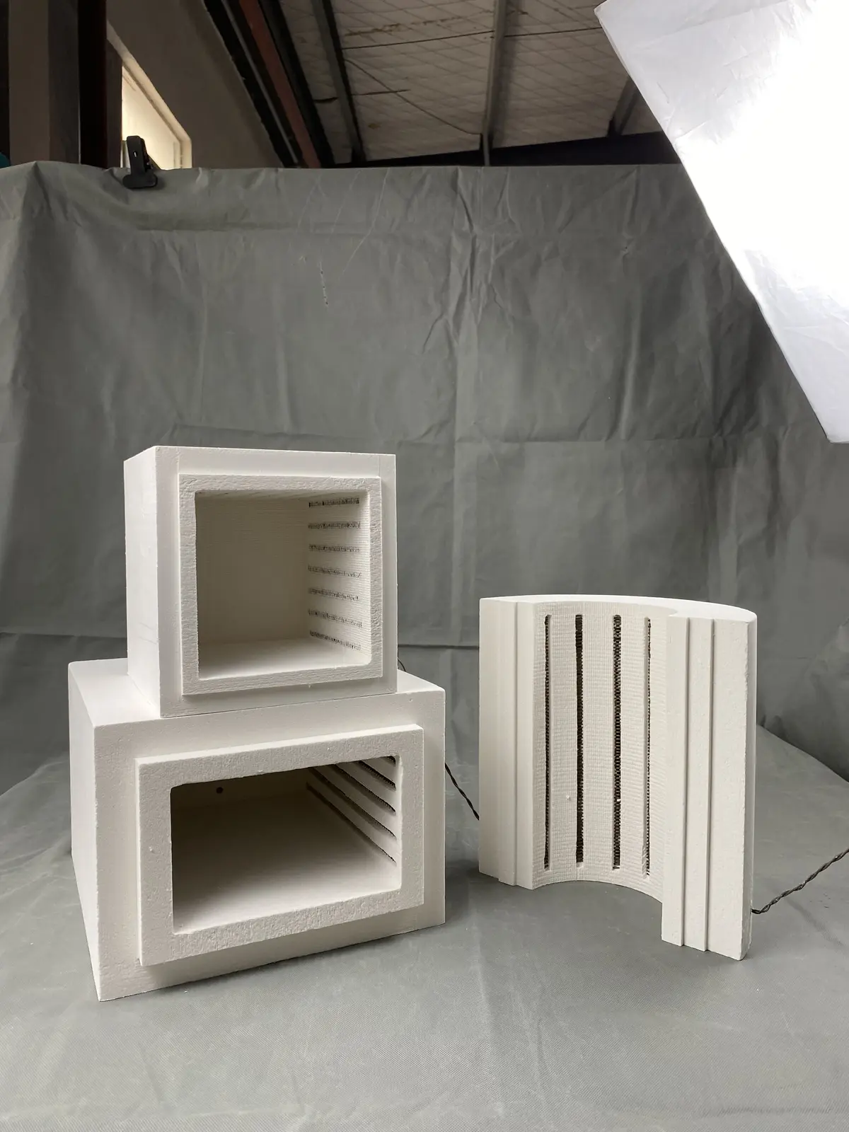
A custom furnace chamber begins with the space that must be heated and the machine that surrounds it. Box, cylindrical, curved and split constructions can be developed for different loads, process tubes, access directions and enclosure limits. Pyrocore treats the chamber as an integrated heated assembly; loose refractory board, blanket and paper are outside this product scope.
Separate internal, chamber and machine dimensions
Provide dimensioned views that distinguish the usable hot space from the insulation body and the surrounding equipment envelope. Mark doors, tube openings, observation or sensor ports, supports, flanges, terminal guards and maintenance clearances. For a replacement project, include both the original chamber dimensions and verified measurements from the machine.
Select a geometry that supports the heat path
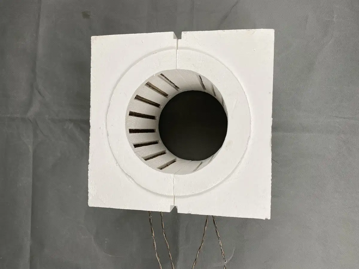
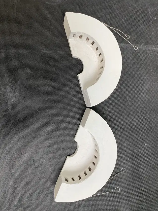
Rectangular chambers suit many front-loading arrangements, while cylindrical and curved sections can follow a tube, vessel or round load. Split constructions allow access around an installed component or process tube. The joint location, movement direction and closing method should be established before the element route is finalized.
Integrate element grooves, zones and terminals
The chamber photographs show several ways of arranging resistance wire within shaped grooves. The final route depends on the required hot zone, available wall area, electrical design and service access. State the supply, power or resistance target, number of control zones and preferred terminal locations. Alternative element systems can be reviewed when supported by the furnace temperature and process duty.
Position sensing around the actual load
Temperature-sensor type and insertion position should be shown on the drawing. The sensor opening, element clearances and load position must not be developed independently. If more than one zone is required, identify the intended zone boundaries and how performance will be evaluated in the assembled equipment.
Define the atmosphere and enclosure boundary
A shaped insulated chamber does not automatically create a vacuum-tight or gas-tight vessel. Identify the component that contains the process atmosphere, its seals and the interface between that boundary and the heated chamber. Also describe ventilation, vapours, contamination sensitivity and any mechanical protection required around the insulation assembly.
Custom chamber RFQ checklist
- Dimensioned internal and external drawings
- Load, tube, crucible or fixture geometry
- Working temperature and complete cycle
- Element type, supply, power or resistance and zone count
- Terminal, lead and sensor positions
- Openings, split lines, movement and mounting details
- Atmosphere, sealing boundary and ventilation conditions
- Equipment photographs, destination and required documentation
For a protective outer enclosure, see Metal-Shelled Furnace Chambers. For measurement-led replacement work, use Furnace Retrofit & Replacement Chambers.