
An integrated heated assembly, not a loose insulation part
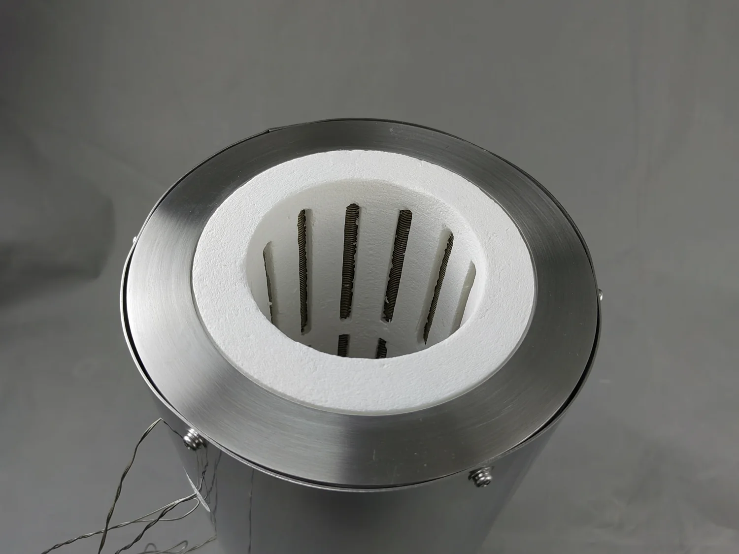
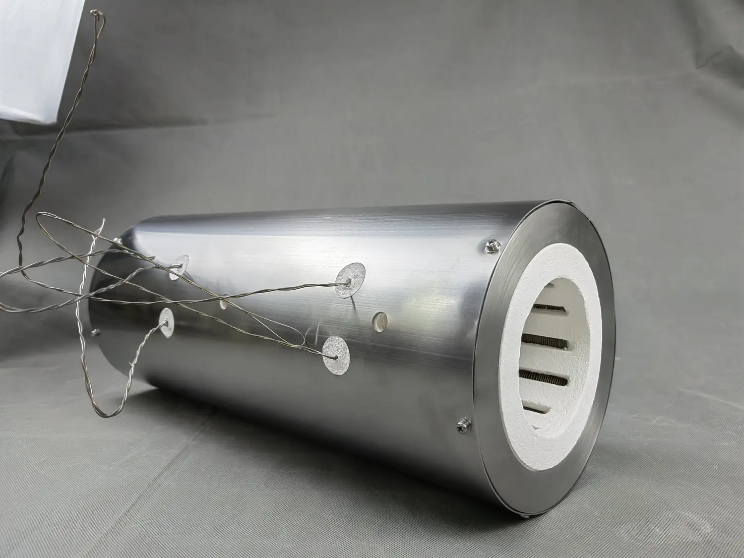
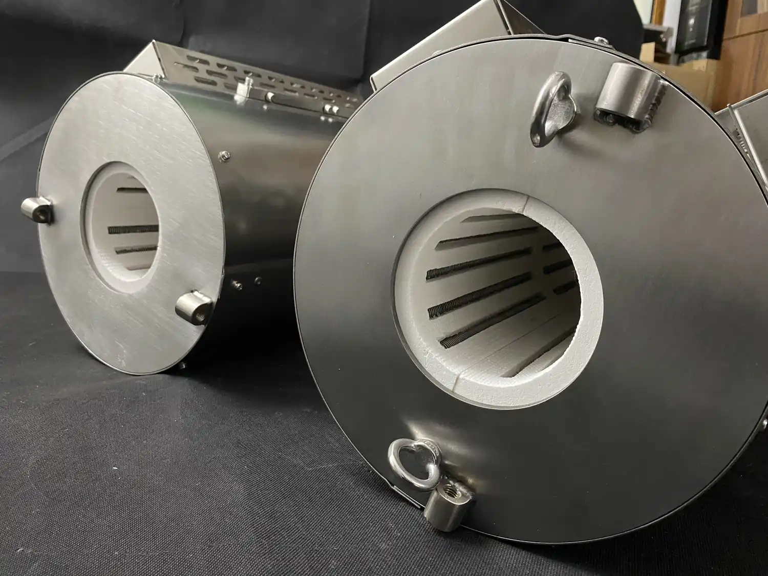
A metal-shelled furnace chamber combines the shaped hot-face and insulation body with installed heating elements, terminals, temperature-sensor provisions and a protective outer shell. It is evaluated as a furnace subsystem for OEM integration or replacement work. Standalone blanket, board and paper are outside this page scope.
Separate usable space from installation dimensions
A replacement or OEM drawing should show at least two boundaries: the space available to the load or process tube, and the external envelope available to the chamber assembly. Include all flanges, brackets, terminal covers, sensor openings and access clearances. A photograph is useful context but does not replace a dimensioned drawing.
Choose the chamber geometry around the process interface
Cylindrical and other shaped assemblies can support tube positions, crucibles, compact hot zones or special equipment layouts. The geometry must follow the actual workpiece, loading direction and surrounding enclosure. If a split construction, removable section or custom opening is required, mark the movement and joint lines on the drawing.
Coordinate elements, terminals and sensing
Heating-element placement influences the hot-zone shape, terminal positions and service access. Provide the available voltage, phase and control arrangement together with any target resistance or power information from the existing design. Temperature-sensor type, insertion direction and relationship to the load should be shown rather than treated as an independent fitting.
Understand the shell boundary
The metal shell protects and supports the insulated heated assembly. It should not be interpreted as proof of a gas-tight or vacuum-rated process vessel. When the surrounding machine uses a sealed tube or chamber, define which component creates the process seal and how the heated assembly interfaces with it.
Replacement and OEM inquiry package
- Dimensioned internal and external views
- Overview photographs of the existing equipment
- Load, tube or crucible geometry
- Working temperature and cycle
- Supply, power, resistance, zones and terminals
- Sensor type and position
- Mounting, movement and service clearances
- Atmosphere or sealing boundary, where applicable
For a general measurement workflow, use Furnace Retrofit & Replacement Chambers.