
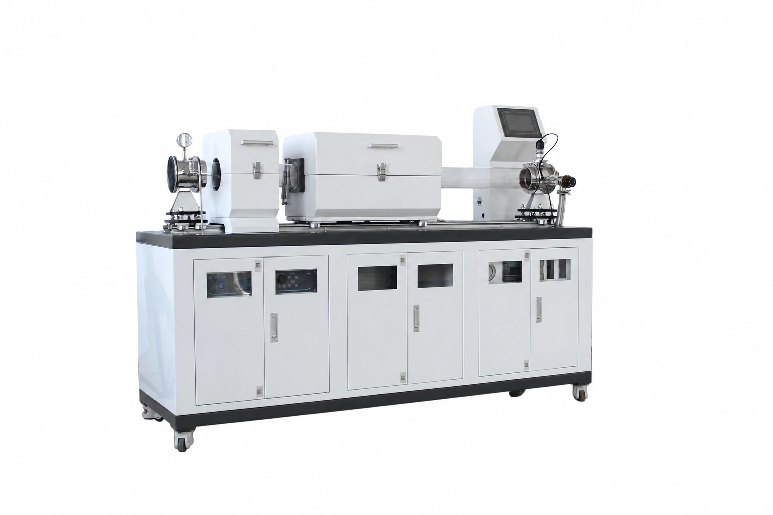
Add the plasma boundary to the complete CVD system
PECVD equipment includes the thermal, gas, pressure and exhaust decisions of a CVD system, with an additional plasma-generation and coupling boundary. The plasma region, process tube, substrate position and heated zone must be coordinated rather than treated as independent accessories.
Coordinate the split furnace and process tube
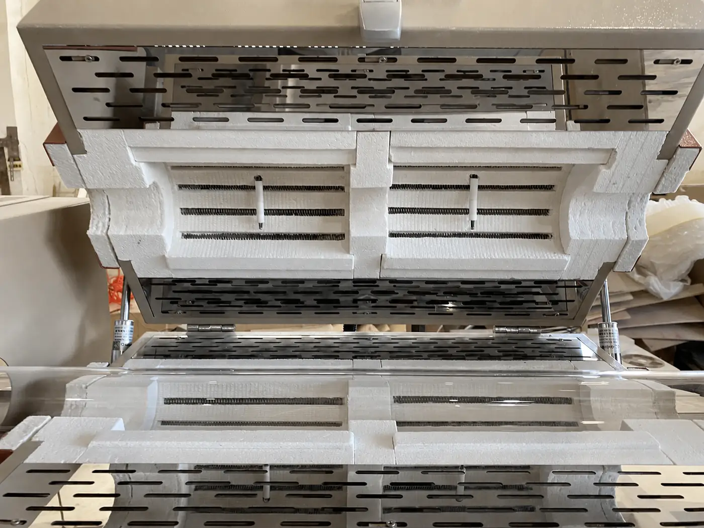
A split furnace can provide access around an installed tube, but bore, heated length, opening direction, tube support and insulation interfaces must match the complete assembly. The chamber image documents the element and insulation arrangement; final dimensions and electrical values remain configuration-specific.
Specify the plasma subsystem clearly
State the required plasma source or coupling approach, intended plasma region and relationship to substrate heating. If an RF generator, matching network, electrodes or other plasma hardware is expected inside the scope, identify the required interfaces and sequence.
Plan maintenance and process cleaning
Deposition equipment must provide practical access to tubes, seals, holders and contaminated process components. Describe cleaning frequency, removable parts, residue concerns and any restrictions on handling or exhaust.
Prepare the technical discussion
- Process objective, substrate and holder geometry
- Required plasma region and source boundary
- Tube material, diameter, length and sealing
- Working temperature, zones and substrate position
- Process and purge gases with available safety information
- Pressure, pumping and exhaust treatment
- Automation, interlocks, data, utilities and destination country