
Project evidence translated into configuration decisions
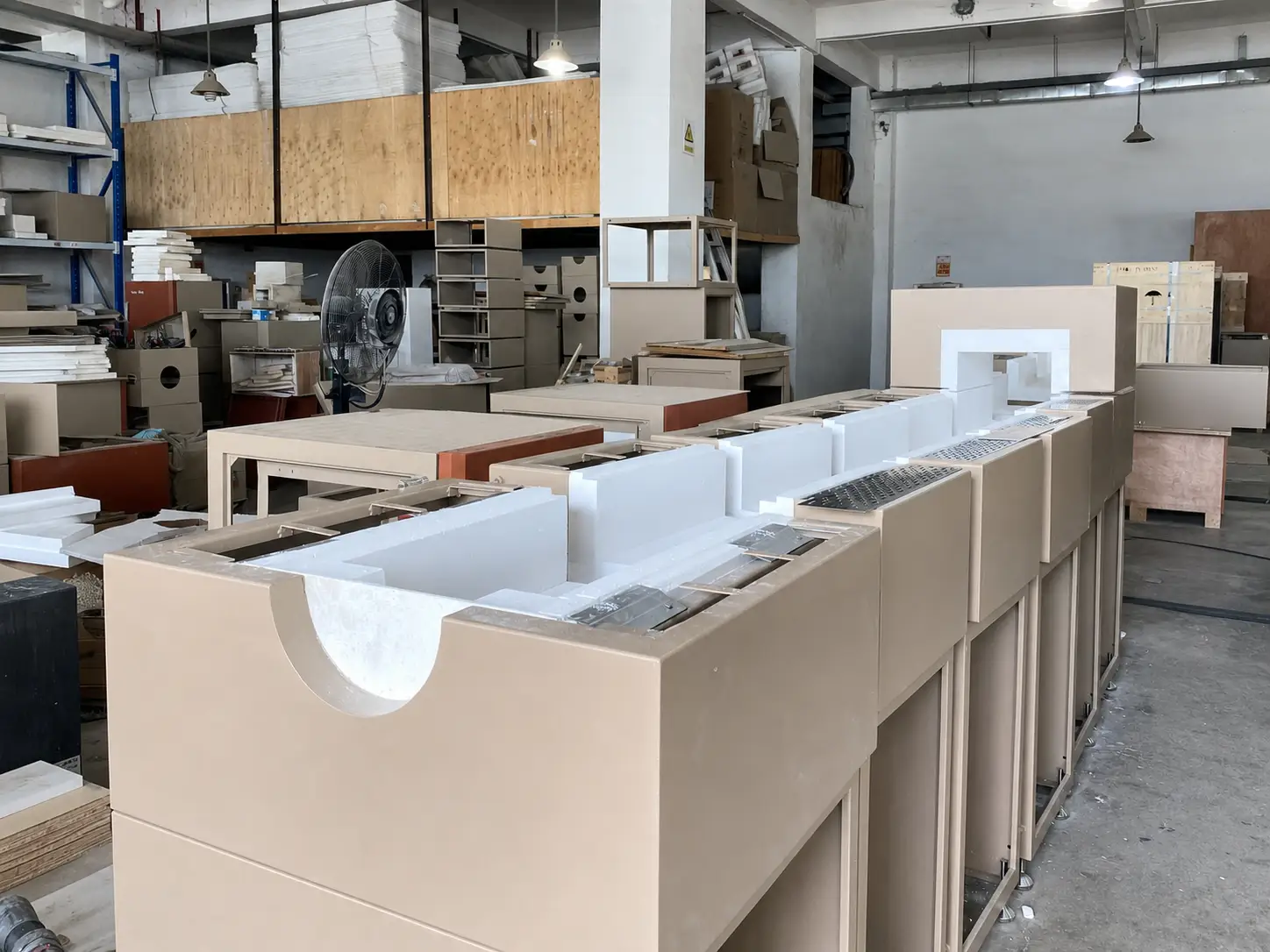
Pyrocore has published three additional furnace configuration case studies covering a long multi-section assembly, a combined vertical and horizontal tube furnace system with five-channel gas control, and a sliding split tube furnace with an extended probe interface. The case library now contains four equipment-configuration studies.
Each study uses real, anonymized equipment evidence to explain how visible geometry and interfaces affect project definition. Customer names, countries, order information, confidential values and process results are not published. The cases do not turn one project into a universal model specification; they show which inputs must be qualified for a similar requirement.
Long furnace assemblies require one axial reference
The long multi-section case shows repeated insulated enclosure sections aligned around a continuous process opening. The visible sections establish physical construction, but do not by themselves prove independent controls or temperature uniformity. A similar project needs one dimensioned axial layout covering the process path, section boundaries, joints, supports, sensors, terminals, service panels and installation access.
Orientation changes loading and interface decisions
The vertical and horizontal system case shows why process-tube orientation must be treated as an application decision. Vertical equipment introduces upper and lower connection, total-height and suspended or gravity-assisted loading questions. Horizontal equipment introduces side loading, flange clearance and tube-end support. Both routes require the mass of fittings, gauges and hoses to be supported without imposing uncontrolled loads on a brittle process tube.
Visible flow channels do not define the gas process
The project photograph shows five flowmeter channels, while the case article separates that visible fact from project-specific performance. A new review must identify every gas, source pressure, purity, required flow, isolation and purge function, mixing location and destination. Flow control is only one part of the environment; seals, pressure measurement, valves, pump and exhaust establish the complete pressure boundary.
Movement and probe position share one geometry
The sliding furnace case connects the guided heating enclosure with a process tube, flange, extended probe and independent support. Furnace travel, heated position, probe tip, sample position, sensor roles, hot-surface protection and cable routing should appear on one drawing. The visible flange and valve prove an interface, not a universal pressure rating, and the inserted probe does not by itself establish a measurement result.
Use the cases to prepare the next discussion
- Select the closest project geometry, not only the closest furnace appearance
- Mark load, tube, sample, sensor, zone and interface positions on a drawing
- Define the complete thermal, atmosphere, movement and operating sequence
- Separate visible equipment evidence from values that require confirmation
- Identify supports, service access, utilities, controls and acceptance evidence
- Send the process objective and constraints for an independent technical review
Review all Case Studies, compare Furnaces, or prepare the project with the Furnace RFQ Checklist.